Manufacturing Technology: Unit III: Reciprocating Machine Tools
gear cutting by forming methods
Reciprocating Machine Tools - Manufacturing Technology
The following forming methods for the manufacture of gears are
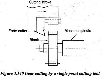
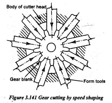
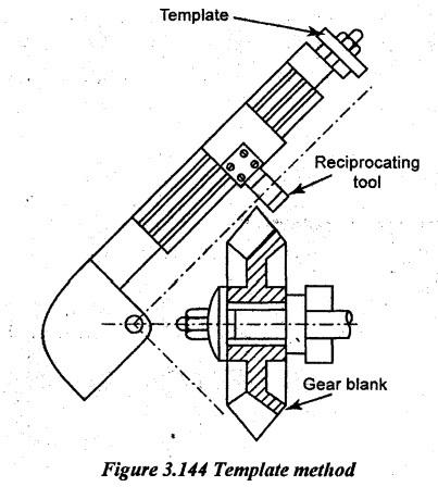
GEAR CUTTING BY FORMING METHODS The following forming methods for the manufacture of gears are 1. Gear cutting by single point form tool 2. Gear cutting by shear speed shaping process 3. Gear milling using a formed end mill 4. Gear broaching 5. Template method. In this case, a single point cutting tool is used for cutting the gear in a shaping machine or planning machine. The cutting edge of the tool is made to the shape of the gear tooth. By using this method, both spur and bevel gears can be cut. The work is mounted between two centres in which the work or tool reciprocates to perform the cutting task. The cutting stroke should exactly be parallel and above the blank axis. So, the blank should be accurately set. By feeding the tool downwards, the depth of cut is given. Figure 3.140 illustrates the process of gear cutting by a single point cutting tool. In this type, the form tools are radially arranged in the cutter head. The number of form tools is equal to the number teeth required on the blank. So, all tooth spaces are cut at the same time by feeding along with tools towards the centre of the blank during cutting stroke. Figure 3.141 illustrates the process of gear cutting by speed shaping process. During return stroke, the tools are radially moved outwards or retracted. It is possible only by giving a relief to the cutting edges. The depth of cut can be adjusted by the radial movement of the tools. Advantages: 1. It is the quickest process. 2. Both external and internal spur gears can be cut. In this type, the cutting edges are formed to the shape of the gear tooth space. The form end mill cutter is held on the spindle of a vertical milling machine. The blank is held in a dividing head and fed against the rotating cutter. The axis of both the cutter and gear blank is perpendicular to each other as shown in Figure 3.142. After completing one tooth space, the work is indexed to complete the next tooth space. Here, only simple indexing is used. where Z be the number of teeth to be cut & assuming N = Z. Spur, helical or herringbone gears (double helical) can be cut in this method with large module. This method is also used to finish the teeth of cast gears. 025842022 This method is mainly used for making internal gears with an accurate shape. Here, the broaching tool has a number of cutting edges equal to the number teeth required on the gear blank. Even very small gear can be cut in a single stroke of the broaching tool. Figure 3.143 illustrates the process of gear broaching process. Generally, the broaching process is used in mass production. But, the broaching is very costly. In this case, a single point cutting tool reciprocates on a frame. One end of the frame is pivoted and the other end is connected with a follower resting on a stationary template as shown in Figure 3.144. The tool movement of the gear profile is guided by the template. The withdrawal is also guided by the template. After completing the tooth space, the blank. is indexed for the next cut.1. Gear Cutting by a Single Point Formed Tool
2. Gear Cutting by Speed Shaping Process
3. Gear Milling using a Form End Mill


4. Gear Broaching
5. Template Method
Manufacturing Technology: Unit III: Reciprocating Machine Tools : Tag: : Reciprocating Machine Tools - Manufacturing Technology - gear cutting by forming methods
Related Topics
Related Subjects

Manufacturing Technology
ME3493 4th semester Mechanical Dept | 2021 Regulation | 4th Semester Mechanical Dept 2021 Regulation