Theory of Machines: Unit IV: Force Analysis
Free body diagram
Force Analysis - Theory of Machines
The primary tool for the engineer in performing force (or load) analysis of machines and structures is the free body diagram or FBD.
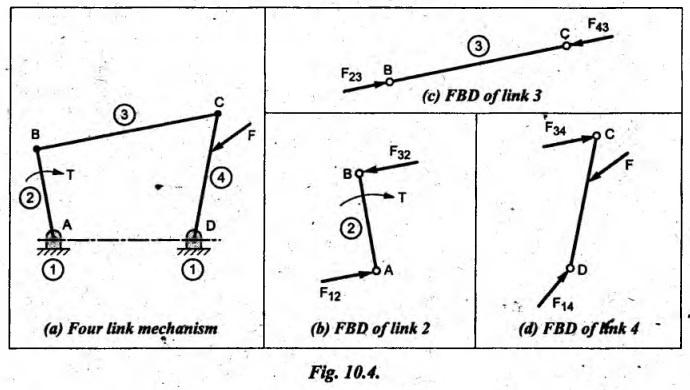
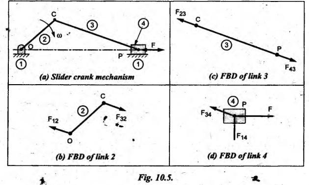
FREE BODY DIAGRAM • The primary tool for the engineer in performing force (or load) analysis of machines and structures is the free body diagram or FBD. In simple terms, a free body diagram is a picture of how the engineer visualizes all the forces (or loads), which are acting on a particular device or a particular part of a device. • To clearly identify the various forces acting on a body in equilibrium, we have to draw its free body diagram. Thus the construction and presentation of clear and neatly drawn free body diagrams represent the heart of engineering communication. They also represent a part of the thinking process. • Definition of FBD: A free body diagram is a sketch or drawing of the body, isolated from the rest of the machine and its surroundings, upon which the forces and moments are shown in action. In other words, a diagram which shows the forces and moments on the body free of other bodies, is called the free body diagram (FBD). 1. A diagram of the body completely isolated from all other bodies is drawn. The free body may consists of entire system or any portion of the system. 2. All the supports (like wall, floor, hinge or any other body) are removed and replaced them by the reaction, which these supports exert on the body. 3. The actions (forces acting) and reactions of the each body are represented in the diagram with their direction and magnitude. 4. The known applied load is shown by its magnitudes and directions, and the unknown applied load by a symbol (or letter). 5. Appropriate dimensions (including slopes or angles) or the coordinates of key points, which are needed in defining the configuration of the force system, are indicated. 6. The weight force of the free body is indicated with vertical downward arrows and is shown like an applied load. 7. The fixed link (member) has no FBD. 8. If the direction of torque on the input is not given, then draw the free body diagrams in the following sequence: (i) Member with two forces. (ii) Member with three forces. (iii) Member with two forces and a torque. 9. If the direction of torque on the input link is given, then draw the free body diagrams of members in the following sequence: (i) Member with two force and a torque. (ii) Member with two forces. (iii) Member with three forces. 10. The procedure is repeated for all the members of the system in equilibrium. Example 10.1 Draw the free body diagrams of the members of a four-link mechanism shown in Fig.10.4(a), so that each member is in equilibrium. Solution: From the given four-link mechanism, it is clear that ■ Member 2 is acted upon by two forces F12 and F32 and a torque T, ■ Member 3 is acted upon by two forces F23 and F43, and ■ Member 4 is acted upon by three forces F, F34 and F14. Since member I is fixed, there is no FBD for link 1. The free body diagrams of link 2, link 3, and link 4 can be drawn as shown in Fig.10.4(b), (c) and (d) respectively. Example 10.2 Draw the free body diagrams of the members of a slider crank mechanism shown in Fig.10.5(a), so that each member is in equilibrium individually. Solution: From the given slider crank mechanism, it is clear that ■ Member 2 is acted upon by two forces F12 and F32, ■ Member 3 is acted upon by two forces F23 and F43, and ■ Member 4 is acted upon by three forces F, F14 and F34. Thus the free body diagrams of link 2, link 3, and link 4 can be drawn as shown in Fig.10.5(b), (c), and (d) respectively.1. Steps Involved in Drawing Free Body Diagram
Theory of Machines: Unit IV: Force Analysis : Tag: : Force Analysis - Theory of Machines - Free body diagram
Related Topics
Related Subjects

Theory of Machines
ME3491 4th semester Mechanical Dept | 2021 Regulation | 4th Semester Mechanical Dept 2021 Regulation