Hydraulics and Pneumatics: Unit V: Trouble Shooting and Applications
Formulae summary for design of hydraulic/pneumatic system
Trouble Shooting and Applications - Hydraulics and Pneumatics
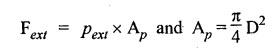
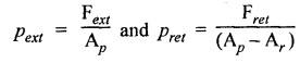
Let Fext and Fret = Force exerted on piston during extension and return strokes respectively,
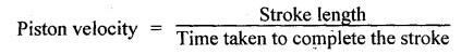
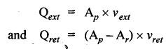
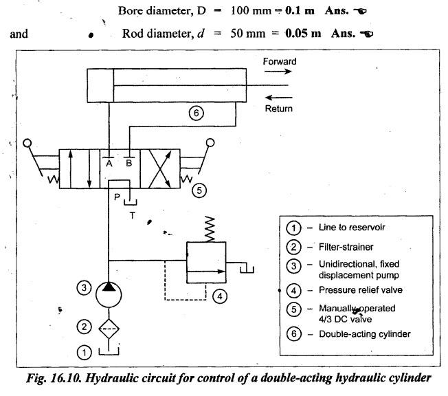
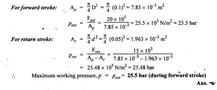
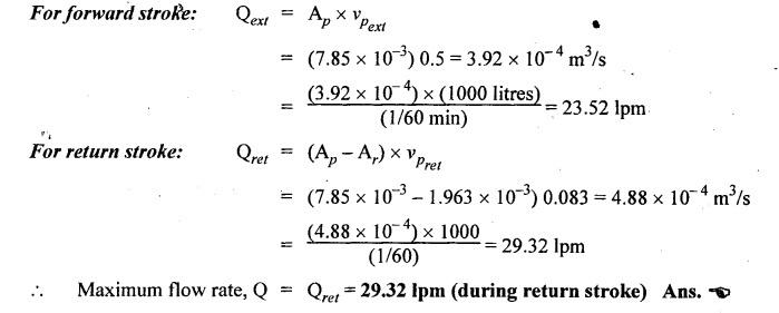
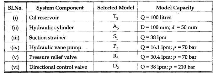
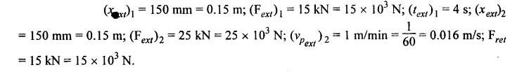
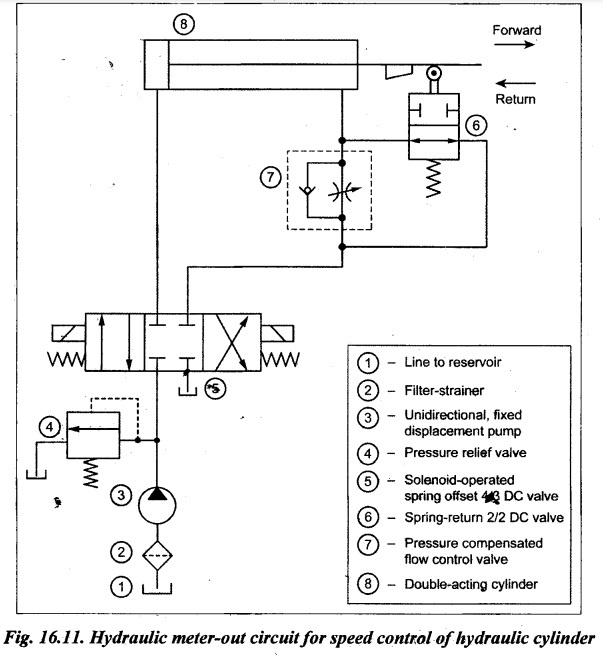
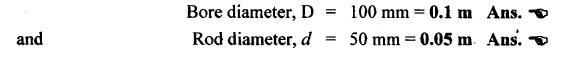
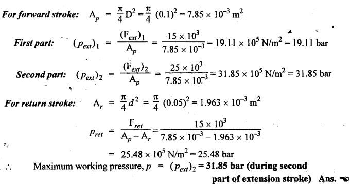
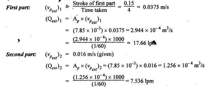
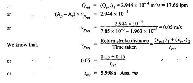
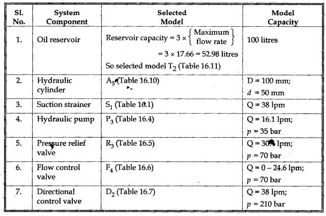
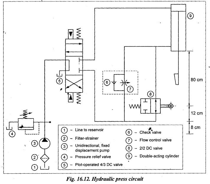
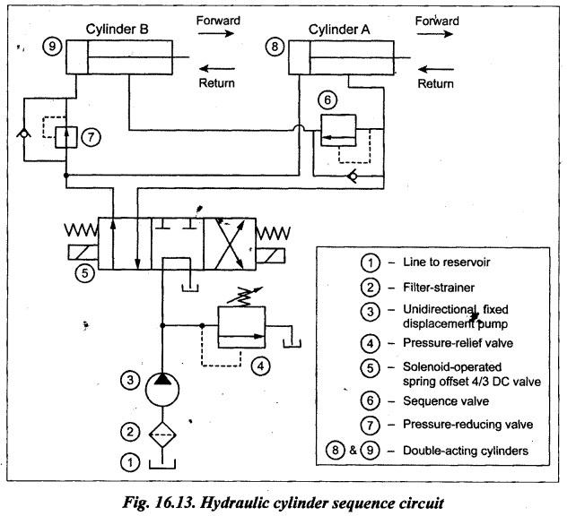
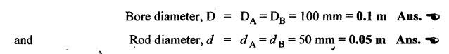
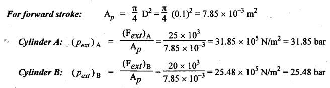
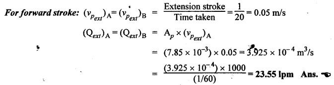
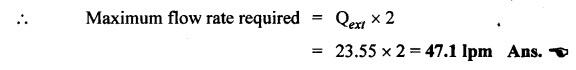
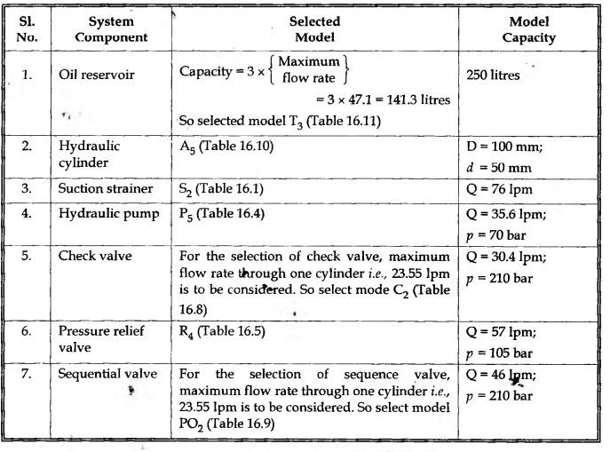
FORMULAE SUMMARY FOR DESIGN OF HYDRAULIC/PNEUMATIC SYSTEM Let Fext and Fret = Force exerted on piston during extension and return strokes respectively, Pext and Pret = Pressure during forward and return strokes respectively, D = Diameter of piston or bore diameter of cylinder, d = Piston rod diameter, Force (or thrust) = Pressure × Area Flow rate (or discharge) = Area × Velocity Work done = Force × Distance (i) To find cylinder bore diameter of cylinder (D): From the above relations, the bore diameter can be calculated. (ii) To find maximum working pressure (p): We know that the maximum working pressure can occur either during forward or return stroke, which can be computed using the following equations. (iii) To find maximum flow rate/discharge (Q): We know that maximum flow rate can occur either during forward or return stroke, which can be computed using the following equations. (iv) To find power (P): We know that Power, P = Maximum working pressure (p) × Maximum Q Using the above calculated values, the various components can be selected from Tables 16.1 to 16.12. Example 16.1 A simple hydraulic circuit is used to operate a hydraulic cylinder of a machine. The load during the forward stroke is 20 kN and that during the return stroke is 15 kN. The forward and return speeds are about 3 m/min and 5 m/min respectively. The total stroke of the cylinder is 300 mm. A provision is required to hold the cylinder anywhere in between the end positions. (i) Draw a simple hydraulic circuit as per the above requirement. (ii) Select the different components used in the circuit. Use the reference catalogue data required for system design from Tables 16.1 to 16.12. Solution: The system design of the required hydraulic circuit is given in three steps. (i) Drawing hydraulic circuit, (ii) Design calculations, and (iii) Selection of components. Step 1: Circuit Diagram For the given requirement, the hydraulic circuit that can be used to control a double-acting cylinder is given in Fig.16.10. For more details on circuit operation, refer to Section 8.4, Chapter 8. When one requires to hold the cylinder in one position, the DCV is to be kept in normal central position. Step 2: Calculation of System Parameters Given Data: (i) To find cylinder bõre diameter (D) of cylinder: Since working pressure is not mentioned in the problem, let us select a model of cylinder from the manufacturer's catalogue initially and for the selected model, we can calculate the working pressure. Note The selected initial model has to be checked for safety at the end by comparing with actual working, pressure. From Table 16.10, selecting cylinder model A5, we get (ii) To find maximum working pressure (p): First let us find Pext & Pret, then maximum value is used as p for selection of system components. (ii) To find maximum flow rate (Q): First let us find Qext and Qret, then the maximum value is used as Q for the selection of system components. The calculated system parameters are: (i) maximum working pressure = 25.5 bar, and (ii) maximum flow rate = 29.32 1pm. Step 3: Selection of System Components Now based on the above calculated system parameters, various components are selected using manufacturer's catalogue. (i) Oil reservoir: By the rule of thumb, the reservoir capacity should be 2 to 3 times the maximum flow rate. ⸫ Capacity = 3 × Q = 3 × 29.32 = 87.96 lpm From Table 16.11, model T2 of capacity of 100 lpm is selected. (ii) Hydraulic cylinder: The cylinder model A5 is already selected. Check for safety: Since cylinder A5 has maximum working pressure of 210 bar which is higher than the actual maximum working pressure (25.5 bar). Thus it is safe. (iii) Suction strainer: From Table 16.1, for maximum flow rate of 29.32 lpm, model S, of capacity is selected. (iv) Hydraulic pump: Flow rate capacity ranging from 23.52 lpm (minimum) and 29.32 Ipm (maximum) is required. From Table 16.4, model P3 having flow capacity of 37.5 lpm at pressure 35 bar is selected. (v) Pressure relief valve: From Table 16.5, for maximum rate of 29.32 1pm and maximum working pressure of 25.5 bar, model R3 (having Q = 30.4 lpm and p = 70 bar) is selected. (vi) Direction control valve: From Table 16.7, for maximum flow rate of 29.32 1pm and maximum working pressure of 25.5 bar, model D2 (having Q = 38 lpm and р = 210 bar) is selected. Summary: The selected system components of the circuit are summarised as shown in Table 16.13. Table 16.13. Selected system components Example 16.2 A maching tool cross-slide is moved by means of a hydraulic system. The motion of the cylinder is as follows: (a) Initially it moves through a distance of 150 mm against a load of 15 kN in about 4 seconds. (b) It is followed by a working stroke of another 150 mm against an effective load of 25 kN. The feed rate during this part of the stroke is required to be 1 m/min. (c) The load during return stroke is 15 kN and the return stroke has to be as fast as possible. A meter-out type of hydraulic circuit is used. (i) Draw a suitable hydraulic circuit which will fulfill these requirements. (ii) Select different components used in the circuit. Use data from the manufacturer's catalogue given in Tables 16.1 to 16.12. Solution: Step 1: Circuit Diagram The meter-out speed control circuit for the given requirement is given in Fig.16.11. It is given that the forward stroke is achieved in two parts. Step 2: Calculation of System Parameters Given Data: (i) To find cylinder bore diameter (D) of cylinder: Initially select cylinder model A5 for better safety from Table 16.10. From Table 16.10, for cylinder model A5, we get (ii) To find maximum working pressure (p): First let us find working pressure during first part of forward stroke, second part of forward stroke and during return stroke; the maximum value is used as p for selection of system components. (iii) To find maximum flow rate (Q): First let us find (Qext)1, (Qext)2 and (Qret); the maximum value is used as Q for the selection of system components. For forward stroke: For return stroke: The return stroke should be faster. In order to find speed of return stroke (vpret) and time for return stroke, the maximum flow rate from forward stroke is considered. Thus the system parameters are: (i) maximum working pressure 31.85 bar, and (ii) maximum flow rate = 17.66 lpm. Step 3: Selection of System Components Now based on the above calculated system parameters, various components are selected using manufacturer's catalogue. The selected system components of the circuit are presented in Table 16.14. Table 16.14. Selected system components Example 16.3 A 50 KN hydraulic press has a stroke of 1 m. The main ram is required to move down with a velocity of about 5 m/min for the first 80 cm against a negligible load. The ram is slowed down to a velocity of 2 m/min for the next 12 cm against a load of 12 kN, followed by the working stroke of last 8 cm developing a maximum force of 50 kN. The cylinder is returned as quickly as possible and is to be held at the top most position. (i) Draw a circuit which will fulfill these requirements. (ii) Select the different components used in the circuit. Use data from the manufacturer's catalogue given in Tables 16.1 to 16.12. Solution: The circuit, design calculations and component selection for the given requirement are very similar to previous example (Example 16.2). In this hydraulic press circuit, the forward stroke (i.e., downward motion of cylinder) is achieved in three parts (first 80 cm, next 12 cm & last 8 cm) and the retraction stroke (i.e., upward motion of cylinder) is as fast as possible. Circuit diagram: A typical hydraulic press circuit for the given requirement is presented in Fig.16.12. Example 16.4 Two identical cylinders A and B are to be operated simultareously. The cylinder A moves against a load of 25 kN while the cylinder B has a load of 20 kN. Both the cylinders have a stroke of 1 m. The working stroke is to be completed in about 20 seconds time. The return stroke of the cylinder B is to start only after the cylinder A is completely retracted. The return speeds are to be as fast as possible. (i) Design a circuit which will fulfill these requirements. (ii) Select the different components you have used in the circuit. Use standard data tables wherever required. Solution: Step 1: Circuit Diagram The circuit for sequencing of two hydraulic cylinders fulfilling the given requirements is presented in Fig.16.13. Since both cylinders are to be operated simultaneously and the loads on both differ, therefore it is necessary to supply oil directly to the cylinder 1 through a pressure reducing valve to cylinder 2. A sequence valve is needed to ensure return of cylinder 2, which starts after full return of cylinder 1. Step 2: Calculations of System Parameters Given Data: (Fext) A = 25 kN = 25 × 103 N; (Fext) B = 20 kN = 20 × 103 N; Stroke = LA = LB = 1 m; (text)A = (text)B = 20 s (i) To find bore diameters of cylinder A and B: Initially select model A5 for both cylinders A and B. From Table 16.10, for both cylinder model A5, we get (ii) To find maximum working pressure (p): For return stroke: Since there is no significant load during return stroke, the working pressure is negligible during return stroke. (iii) To find maximum flow rate (Q): For return stroke: Since both cylinders A and B are of same size and the flow of oil are equal, therefore (Qret) A = (Qret) B = (Qext) A = 23.55 lpm Since cylinders A and B simultaneously require flow, Thus the system parameters required for selection of components are: (i) maximum working pressure, p = 31.85 bar; and (ii) maximum flow rate, Q = 47.1 1pm. Step 3: Selection of System Components Now based on the above calculated system parameters, various components are selected using manufacturer's catalogue. The selected system components of the circuit are presented in Table 16.15. Table 16.15. Selected system components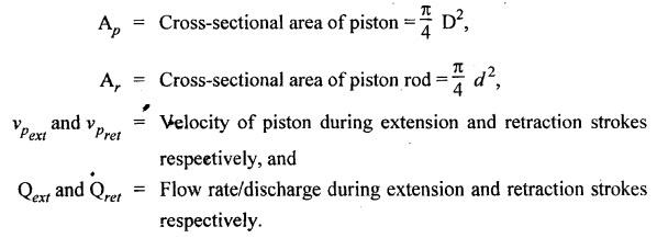


Hydraulics and Pneumatics: Unit V: Trouble Shooting and Applications : Tag: : Trouble Shooting and Applications - Hydraulics and Pneumatics - Formulae summary for design of hydraulic/pneumatic system
Related Topics
Related Subjects

Hydraulics and Pneumatics
ME3492 4th semester Mechanical Dept | 2021 Regulation | 4th Semester Mechanical Dept 2021 Regulation