Theory of Machines: Unit IV: Force Analysis
forces on the reciprocating parts of an engine, neglecting the weight of the connecting rod
Force Analysis - Theory of Machines
Fig.11.2 shows the various forces acting on the reciprocating parts of a horizontal engine.
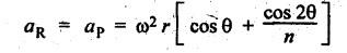
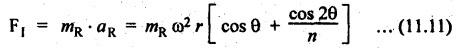
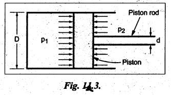
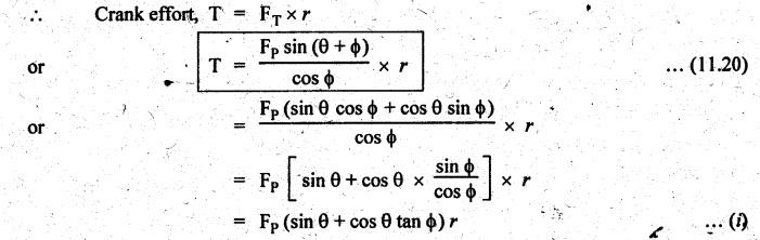
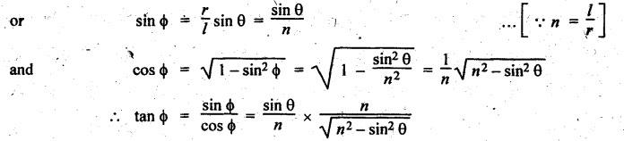
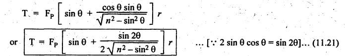
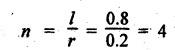
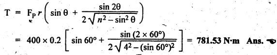
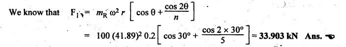
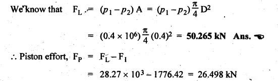
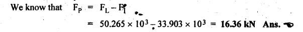
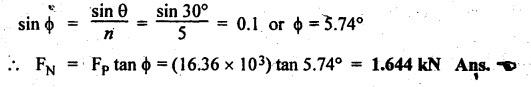
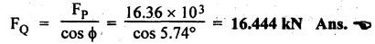
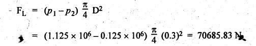
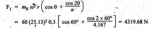
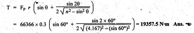
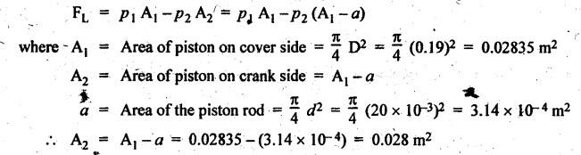
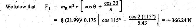
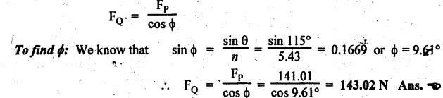
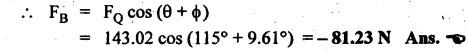
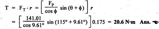
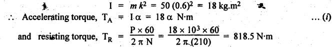
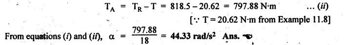
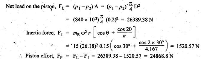
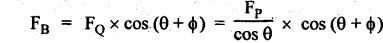
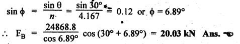
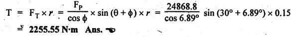
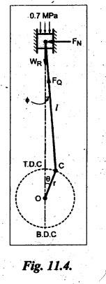
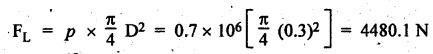
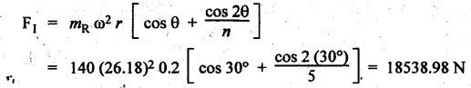
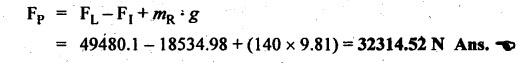
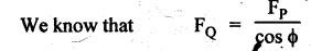
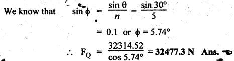
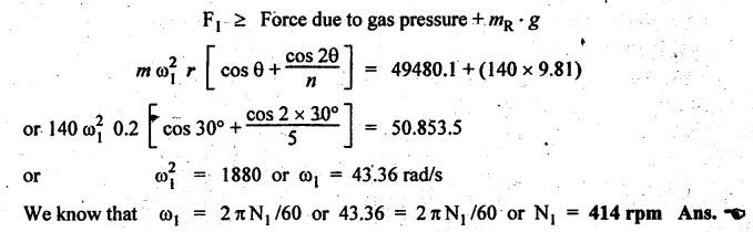
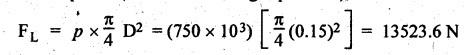
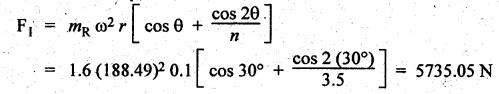
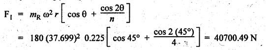
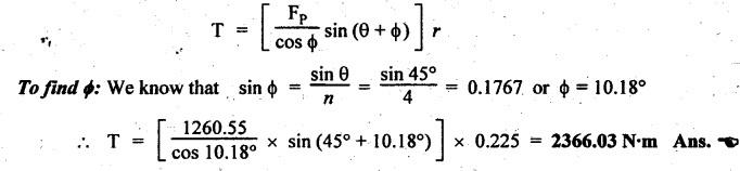
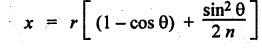
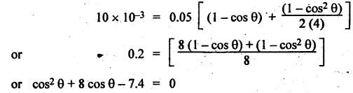
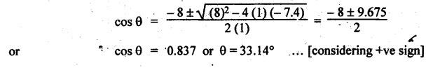
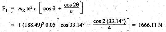
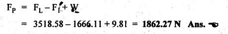
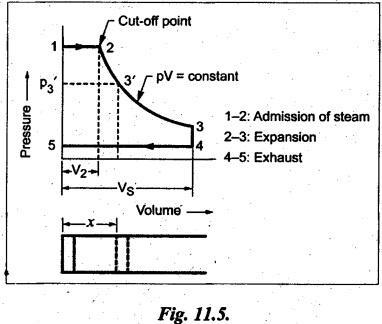
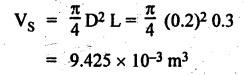
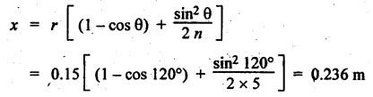
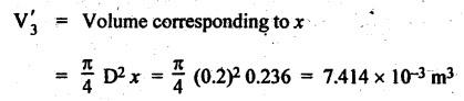
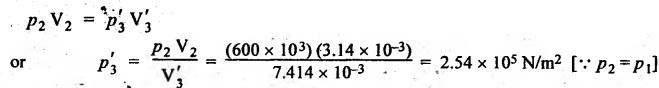
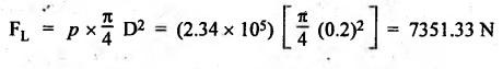
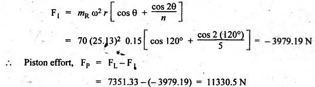
FORCES ON THE RECIPROCATING PARTS OF AN ENGINE, NEGLECTING THE WEIGHT OF THE CONNECTING ROD Fig.11.2 shows the various forces acting on the reciprocating parts of a horizontal engine. The crank OC or radius & rotating in clockwise direction about O. In the configuration shown, the crank has moved angle θ from its IDC. From O, draw a line perpendicular to PO meeting PC produced at point M. Then draw a line CN perpendicular to OC. Let mR = Mass of the reciprocating parts, i.e., piston, cross-head or gudgeon pin, etc. WR = mR • g = Weight of the reciprocating parts, FI = Inertia force or accelerating force of the reciprocating parts, FL = Net load on the piston, FP = Piston effort, FQ = Force acting along the connecting rod, FN = Thrust on the sides of the cylinder walls or normal reaction on the guide bars, FT = Crank-pin effort, FB = Thrust on crankshaft bearings, and T = Crank effort or turning moment on the crankshaft. The expressions for the above-mentioned forces, neglecting the weight of the connecting rod, may be derived as discussed below. • Piston effort is defined as the net or effective force applied on the piston, along the line of stroke. It is denoted by FP. • We know that acceleration of the reciprocating parts or piston, ⸫ Accelerating force or inertia force of the reciprocating parts or piston, The inertia force will be equal and opposite to accelerating force. (a) For horizontal reciprocating engines: When the piston accelerates, the inertia force will act in the direction ←; when the piston retards, the inertia force will act in the direction → with reference to the mechanism shown in Fig.11.2. ⸫ Piston effort, FP = Net load on the piston ± Inertia force = FL + FI ….(neglecting frictional resistance) = FL± FI - RF …..(considering frictional resistance) ... (11.12) where RF = Frictional resistance In equation (11.12), the +ve sign is used when the piston is retarded, and -ve sign is used when the piston is accelerated. (b) For vertical reciprocating engines: In case of a vertical engine, the weight of the reciprocating parts adds to the piston effort during downward stroke and opposes during upward stroke. • To find net load on the piston (FL): (i) For single-cylinder single-acting engine Let p = Net pressure of steam or gas on the piston in N/m2, and D = Diameter of the piston in m. Then net load on the piston is given by (ii) For single-cylinder double-acting engine Consider a double-acting engine shown in Fig.11.3, in which pressure is acting on both sides of the piston. Let p1 and A1 = Pressure and cross sectional area on the back end side of the piston respectively, p2 and A2 = Pressure and cross-sectional area on the crank end side of the piston respectively. a = Cross-sectional area of the piston rod = π/4 d2, and d = Diameter of the piston rod. Then net load on the piston is given by From the geometry of Fig.11.2, we have From the geometry of the Fig.11.2, FN is given by • The force acting on the connecting rod Fo can be resolved into two components, one perpendicular to the crank and the other along the crank. The component of Fo perpendicular to the crank is known as crank-pin effort and it is denoted by FT. • From triangle CNR, • The component of FQ along the crank produces a thrust on the crankshaft bearings. • Resolving FQ along the crank, we get • Crank effort is the net effort (force) applied at the crank pin perpendicular to the crank, which gives the required turning moment on the crankshaft. • Crank effort is the product of the crank-pin effort (FT) and the crank pin radius (r). In the above expression, ϕ can be expressed in terms of θ. We know that l sin ϕ = r sin θ Substituting the value of tan ϕ in equation (i), we get Example 11.5 A force of 4000 N is applied on a piston along the line of stroke of a horizontal steam engine. When the crank is at 60° to IDC, calculate the torque on the crank shaft, when the length of connecting rod is 0.8 m and the length of stroke is 0.4 m. Given data: FP = 4000 N; θ = 60°; l = 0.8 m; L = 0.4 m or r = L/2 = 0.4/2 = 0.2 m Solution: We know that the torque on the crank shaft, Example 11.6 The lengths of crank and connecting rod of a horizontal engine are 200 mm and 1 m respectively. The crank is rotating at 400 rpm. When the crank has turned through 30° from the inner dead centre, the difference of pressure between cover and piston rod is 0.4 N/mm2. If the mass of the reciprocating parts is 100 kg and cylinder bore is 0.4 metres, then calculate: (i) inertia force, (ii) force on piston, (iii) piston effort, (iv) thrust on the sides of the cylinder walls, (v) thrust in the connecting rod, and (vi) crank effort. Given data: r = 200 mm = 0.2 m; l = 1 m; N = 400 rpm; θ = 30°; p1 - p2 = 0.4 N/m2 = 0.4 × 10⁶ N/m2; mg = 100 kg; D = 0.4 m. Solution: ω = 2πN/60 = 2π (400)/60 = 41.89 rad/s and n = l/r = 1/0.2 = 5 (i) Inertia force (F1) : (ii) Net load on the piston (FL): (iii) Piston effort (FP): (iv) Thrust on the sides of the cylinder walls (FN): We know that pressure on the sidebars, FN = FP tan ϕ To find ϕ : We know that (v) Thrust in the connecting rod (FQ): We know that thrust in the connecting rod, (vi) Crank effort (T) We know that tangential force on the connecting rod, FT = FQ sin (θ + ϕ) = 16.444 × 10³ sin (30° + 5.74°) = 9.605 kN We know that turning moment on the crankshaft, T = FT × r Example 11.7 A horizontal steam engine running at 240 rpm has a bore of 300 mm and stroke 600 mm. The connecting rod is 1.25 m long and the mass of reciprocating parts is 60 kg. When the crank is 60o past its inner dead centre, the steam pressure on the cover side of the piston is 1.125 N/mm2 while that on the crank side is 0.125 N/mm2. Neglecting the area of the piston rod, determine: (a) the force on the piston rod, and (b)" the turning moment on the crankshaft. Given data: N = 240 rpm; D = 300 mm = 0.3 m; L = 600 mm = 0.5 m or r = L/2 0.6/2 = 0.3 m; l = 1.25 m; mR = 60 kg; θ = 60°; p1 = 1.125 N/mm2 = 1.125 × 10⁶ N/m2; p2 = 0.125 N/mm2 = 0.125 × 10⁶ N/m2: Solution: ω = 2πN/60 = 2 π (240)/60 = 25.13 m/s and n = l/r = 1.25/0.3 = 4.167 (a) Force on the piston rod i.e., piston effort (FP): We know that net load on the piston, Inertia force on reciprocating parts is given by ⸫ Force on the piston rod or piston effort (b) Turning moment on the crankshaft (T): We know that turning moment on the crankshaft, Example 11.8 A horizontal steam engine running at 210 rpm has a bore of 190 mm and stroke of 350 mm. The piston rod is 20 mm in diameter and connecting Fod length is 950 mm. The mass of the reciprocating parts is 8 kg and the frictional resistance is equivalent to a force of 350 N. Determine the following when the crank is at 115°from the inner dead centre, the mean pressure being 4500 N/m2 on the cover side and 100 N/m2 on the crank side: 1. thrust on the connecting rod, 2. thrust on the cylinder walls, 3. load on the bearings, and 4. turning moment on the crankshaft. Given data: N = 210 rpm; D = 190 mm = 0.19 m; L = 350 mm = 0.35 m or r = 0.35/2 = 0.175 m; d = 20 mm = 0.02 m; l = 950 mm = 0.95 m; mg = 8 kg; RF = 350 N; θ = 115°; p1 = 500 N/m2; p2 = 100 N/m2 Solution: ω = 2πN/60 = 2 π (210)/60 = 21.99 rad/s and n = l/2 = 0.95/0.175 = 5.43 First of all, let us find out the piston effort (FP). ⸫ Piston effort, FP = FL - FI - RF ….(considering frictional resistance) To find net load on the piston (F1): We know that in a double-acting reciprocating engine, net load on the piston is Net load on the piston, FL = (4500 × 0.02835) – (100 × 0.028) = 124.77 N To find inertia force (FI): Therefore, piston effort is given by FP = FL - FI - RF = 124.77- (-366.24) - 350 = 141.01 N 1. Thrust on the connecting rod (FQ): We know that thrust on the connecting rod, 2. Thrust on the cylinder walls (FN): We know that thrust on the cylinder walls, 3. Load on the bearings (FB): We know that load on the bearings, 4. Turning moment on the crank shaft (T): The turning moment on the crankshaft is given by Example 11.9 For the previous example problem, determine the acceleration of the flywheel, if the power of the engine is 18 kW, mass of the flywheel 50 kg and radius of gyration 0.6 m. Given data: P = 18 kW = 18 × 103 W; m = 50 kg; k = 0.6 m Solution: We know that mass moment of inertia of the flywheel, The accelerating torque is equal to the difference of torques on the crankshaft i.e., turning moment (T)) and the resisting torque (TR). Therefore accelerating torque Example 11.10 A steam engine 200 mm bore and 300 mm stroke has a connecting rod 625 mm long. The mass of the reciprocating parts is 15 kg and the speed is 250 rpm when the crank is at 30° to the inner dead centre and moving outwards, the difference in steam pressure is 840 kN/m2. If the crank pin radius is 30 mm, determine: (i) the force on the crankshaft, and (ii) the torque acting on the frame. Given data: D = 200 mm = 0.2 m; L 300 mm or r = 300/2 = 150 mm = 0.15 m; l = 625 mm = 0.625 m; mR = 15 kg; N = 250 rpm; θ = 30°; p1 - p2 = 840 kN/m2 = 840 × 103 N/m2 Solution: ω = 2πN/60 = 2 π (250)/60 = 26.18 rad/s and n = l/r = 0.625/0.15 = 4.167 First let us find out the piston effort (FP). (i) Force on the crankshaft (FB): We know that the force acting on the crankshaft bearing, To find ϕ: We know that (ii) Torque acting on the frame (T): We know that torque acting on the frame, Example 11.11 A singe-cylinder vertical engine has a bore of 300 mm and a stroke of 400 mm. The connecting rod is 1000 mm long. The mass of the reciprocating parts is 140 kg. On the expansion stroke with the crank at 30° from the top dead centre, the gas pressure is 0.7 MPa. If the engine runs at 250 rpm, determine: (i) net force acting on the piston, (ii) resultant load on the gudgeon pin, (iii) thrust on the cylinder walls, and (iv) the speed abóve which other things remaining same, the gudgeon pin loads would be reversed in direction. Given data: D = 300 mm = 0.3 m; L = 400 mm = 0.4 m or r = 0.4/2 = 0.2 m; l = 1000 m; mg = 140 kg; θ = 30°; p = 0.7 MPa = 0.7 × 10⁶ N/m2; N = 250 rpm Solution: ω = 2πN/60 = 2л (250)/60 = 26.18 rad/s and n = l/r = 1/0.2 = 5 (i) Net force acting on the piston (FP): The configuration diagram of a vertical engine is shown in Fig.11.4. We know that force due to gas pressure, Inertia force on the piston is given by We know that for a vertical engine, net force on the piston, (ii) Resultant load on the gudgeon pin (FQ): To find ϕ: (iii) Thrust on the cylinder walls (FN): (iv) The speed above which the gudgeon pin load would be reversed in direction: The gudgeon pin load (FQ) will be reversed in direction, if FQ becomes negative. This is possible only when FP is negative. Therefore for FP to be negative, F1 must be greater than (FL + WR). That is Example 11.12 A vertical petrol engine 150 mm diameter and 200 mm stroke has a connecting rod 350 mm long. The mass of the piston is 1.6 kg and the engine speed is 1800 rpm. On the expansion stroke with crank angle 30°from top dead centre, the gas pressure is 750 kN/m2. Determine the net thrust on the piston. Given data: D = 150 mm = 0.15 m; L = 200 mm = 0.2 m or r = 0.2/2 = 0.1 m; l = 350 mm = 0.35 m; mR = 1.6 kg; N = 1800 rpm; θ = 30°; p = 750 kN/m2 = 750 × 103 N/m2 Solution: ω = 2πN/60 = 2 π (1800)/60 = 188.49 rad/s and n = l/r = 0.35/0.1 = 3.5 We know that net load on the piston (i.e., force due to gas pressure), We also know that inertia force on the piston, For vertical engine force acts because of mass piston, therefore WR = mR • g = 1.6 × 9.81 = 15.696 N ⸫ The net thrust on the piston (ie, piston effort) is given by Example 11.13 A vertical single-cylinder engine has a cylinder of 250 mm and stroke length 450 mm. The reciprocating parts have a mass of 180 g. The connecting rod is four times the crank radius and the speed is 360 rpm. When the crank has turned through an angle at 45° from top dead centre, the net pressure on the piston is 1.05 MN/m2. Calculate the effective turning moment on the crankshaft for this position. Given data: D = 250 mm = 0.25 m; L = 450 mm = 0.45 m or r = 0.45/2 = 0.225 m; mR = 180 kg; l = 4 r = 4 (0.225) = 0.9 m; N = 360 rpm; θ = 45°; p = 1.05 MN/m2 = 1.05 × 10⁶ N/m2. Solution: ω = 2πN/60 = 2π (360)/60 = 37.7 rad/s and n = l/r = 4 Net load on the piston (i.e., force due to pressure on piston) is given by Inertia force on the piston is given by Weight of the reciprocating parts is given by W = mR • g = 180 × 9.81 = 1765.8 N We know that the piston effort (i.e., net force acting on the piston) of a vertical engine, FP = FL - FI + W = 51541.75 - 40700.49 + 1765.8 = 12607.55 N Then the turning moment on the crankshaft is given by Example 11.14 The ratio of the connecting rod length to crank length for a vertical petrol engine is 4: 1. The bore/stroke is 80/100 mm and mass of the reciprocating part is 1 kg. The gas pressure on the piston-is 0.5 N/mm2 when it has moved 10 mm from TDC on its power stroke. Determine the net load on the gudgeon pin. The engine runs at 1800 rpm. At what engine speed will this load be zero? Given data: n = l/r = 4; D/L = 80/100 mm or D = 80 mm = 0.08 m and L = 100 mm = 0.1 m or r = 0.1/2 = 0.05 m; mR = 1 kg; p = 0.7 N/mm2 = 0.7 × 10⁶ N/m2; x = 10 mm = 10 × 10-3 m; N = 1800 rpm. Solution: ω = 2лN/60 = 2π (1800)/60 = 188.49 rad/s We know that displacement of piston, where θ = Angular position of crank. Substituting the values of x, r and n, we can determine the value of θ, as below. Solving the above quadratic equation in cos θ, we get 1. Net load on the gudegeon pin (i.e., piston effort) (FP): We know that net load on the piston, The inertia force on the piston is given by Weight of the piston acting downwards is given by W = mR • g = 1 (9.81) = 9.81 N Therefore, the net load on the gudgeon pin is given by 2. Engine speed at which FP is zero: The value of FP will be zero, only when the value of (FL + W) is equal to F1 value. i.e., FL + W = F1 Example 11.15 A horizontal, double-acting steam engine has a stroke of 300 mm and runs at 240 rpm. The cylinder diameter is 200 mm, connecting rod is 750 mm long and the mass of the reciprocating parts is 70 kg. The steam is admitted at 600 kN/m2 for one third of the stroke, after which expansion takes place according to the hyperbolic law pV = constant. The exhaust pressure is 20 kN/m2. Neglecting the effect of clearance and the diameter of the piston rod, find: 1. thrust on the connecting rod, and 2. effective turning moment on the crankshaft when the crank has turned through 120° from inner dead centre. Given data: L = 300 mm = 0.3 m or r = 0.3/2 = 0.15 m; N = 240 rpm; D = 200 mm = 0.2 m; l = 750 mm = 0.75 m; mR = 70 kg; p1 = 600 kN/m2; p5 = 20 kN/m2; = 120° Solution: ω = 2πN/60 = 2 π (240)/60 = 25.13 rad/s and n = l/r = 0.75/0.15 = 5 First of all, let us find the piston effort (FP). The pressure-volume (p-V) diagram for a steam engine neglecting clearance P3 is shown in Fig.11.5. In Fig.11.5, 1-2 represents the admission of steam, 2-3 the expansion and 4-5 the exhaust of steam. The steam is cut-off at point 2. We know that the stroke volume, Since the steam is cut-off at 1/3rd of the stroke, hence volume of steam at cut-off When the crank position is 120° from the IDC (i.e., when θ = 120°), the displacement of the piston (marked by point 3' on the expansion curve 2-3) is given by Corresponding to θ = 120°, the piston is at x = 0.236 m, the volume of point 3' is given by Since the expansion is hyperbolic (i.e., according to the law pV = constant), therefore ⸫ Difference of pressures on the two sides of the piston, We know that net load on piston, and inertia force on the reciprocating parts, 1. Thrust on the connecting rod (FQ): 2. Effective turning moment on the crankshaft (T):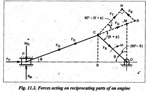
1. Piston Effort (or Effective Driving Force or Net Load on the Gudgeon Pin) (FP)


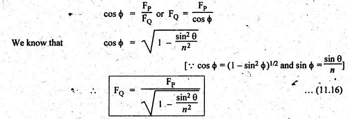
2. Force Acting along the Connecting Rod (FQ)
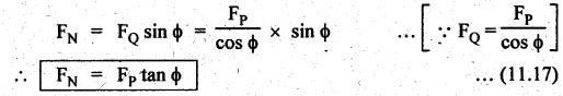
3. Thrust on the Sides of Cylinder Walls (or Normal Reaction on the Guide Bars) (FN)
4. Crank-Pin Effort (FT)
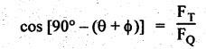

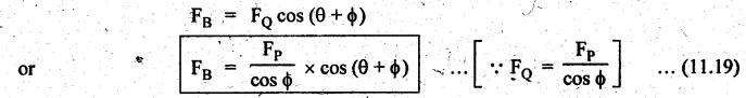
5. Thrust on Crank Shaft Bearing (FB)
6. Crank Effort (or Turning Moment or Torque on the Crankshaft) (T)


Theory of Machines: Unit IV: Force Analysis : Tag: : Force Analysis - Theory of Machines - forces on the reciprocating parts of an engine, neglecting the weight of the connecting rod
Related Topics
Related Subjects

Theory of Machines
ME3491 4th semester Mechanical Dept | 2021 Regulation | 4th Semester Mechanical Dept 2021 Regulation