Hydraulics and Pneumatics: Unit IV: Pneumatic and Electro Pneumatic Systems
fluidic control of fluid power systems
Pneumatic and Electro Pneumatic Systems - Hydraulics and Pneumatics
Because of the many advantages of the fluidic control systems (discussed in Section 15.2.2), they are widely used in many fluid power applications.
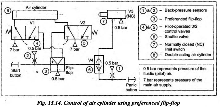
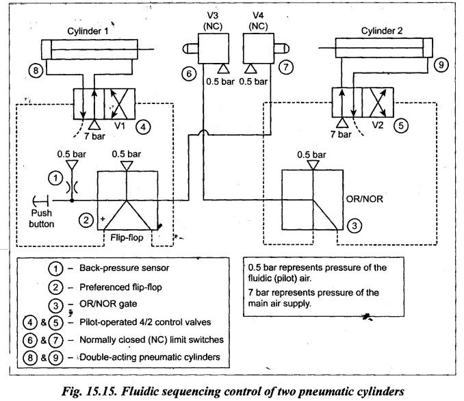
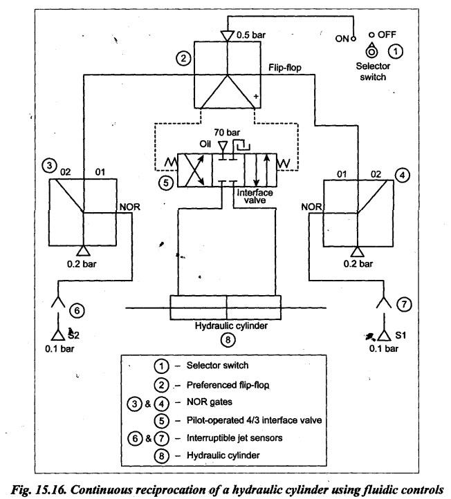
FLUIDIC CONTROL OF FLUID POWER SYSTEMS Because of the many advantages of the fluidic control systems (discussed in Section 15.2.2), they are widely used in many fluid power applications. Now we shall discuss three basic circuits where fluidics is used to control the fluid power systems. It may be noted that fluidic circuits operate at low pressures (normally less than 1 bar) to provide the necessary logic functions to pilot-operate pneumatic valves for the control of fluid power. It should be noted that the fluidic air and air lines are kept separate from the main air supply (having high pressures from 7 bar to 10 bar) utilized by pneumatic systems. 1. Circuit Fig.15.14 illustrates a fluidic logic circuit that can provide the push-button start and air limit switch reversal of an air cylinder. This circuit uses two pilot-actuated 3/2 control valves (V1 and V2), a preference flip-flop, a normally closed (NC) limit switch (V3), a shuttle valve (V4), and an air cylinder. 2. Operation The start and panic buttons represent back-pressure sensors to allow 0.5 bar nozzle- restricted air supplies to activate the control ports of the preferenced flip-flop. The operation of this circuits is as follows: 1. When the START button is pressed momentarily, the preferenced flip-flop actuates the interface 3/2 control valve V1 using 0.5 bar fluidic (pilot) air. 2. Now the 3/2 control valve V1 allows the main supply, air (having 7 bar pressure) to the blind end of the air cylinder and thus the cylinder extends. 3. When the cylinder reaches its maximum stroke, the normally closed (NC) limit switch V3 is actuated. This limit switch V3 now supplies 0.5 bar pilot air through the shuttle valve V4 to switch the flip-flop. 4. When the flip-flop is switched, the pilot air actuates the interface 3/2 control valve V2. 5. Now the 3/2 control valve V2 allows the main supply air (having 7 bar pressure) to the rod end of the air cylinder and thus the cylinder retracts. 6. In the circuit, the panic button is used to override the air limit switch. For instance, if the panic button is momentarily pressed while the cylinder is extending, it will cause the cylinder to retract instantly. 7. The flip-flop with a start-up preference is used to prevent the cycle from starting automatically as soon as the fluidic and pneumatic air supplies are turned on. 1. Circuit Fig.15.15 illustrates a fluidic logic circuit that shows the fluidic sequencing control of two pneumatic cylinders. This circuit uses two pilot-operated 4/2 control valves V1 and V2), a preferenced flip-flop, an OR/NOR gate, two normally closed (NC) air limit switches (V3 and V4), and two pneumatic cylinders. 2. Operation Let us consider the following sequencing of operations: (i) Cylinder 1 extends, (ii) Cylinder 2 extends, and (iii) Cylinders 1 and 2 retract together. Assume that initially both cylinders are in fully retracted position. The operation of this sequencing circuit is as follows : 1. When the push button is pressed momentarily, the preferenced flip-flop (using 0.5 bar air) pilot-actuates interface 4/2 control valve V1 to extend the cylinder 1 with 7 bar air. 2. When the cylinder 1 is extended fully, the normally closed (NC) limit switch V3 is actuated. Now V3 supplies 0.5 bar pilot signal through the OR/NOR gate to actuate the interface 4/2 control valve V2. Now the cylinder 2 extends. 3. When both cylinders are extended fully, both limit switches V3 and V4 are actuated. Now V4 supplies 0.5 bar pilot signal through the flip-flop to shift the interface 4/2 control valve V1. Now the 7 bar main air from the V1 flows into the rod end of the cylinder 1 and thus cylinder 1 retracts. At the same time, V3 supplies 0,5 bar pilot signal through the OR/NOR gate to shift the interface 4/2 control valve V2. Now the 7 bar main air from the V2 flows into the rod end of the cylinder 2 and thus the cylinder 2 retracts. Thus both cylinders retract together at the same time. 4. The cycle can be repeated by momentarily pressing the push button each time. 1. Circuit Fig.15.16 illustrates a fluidic logic circuit that controls the continuous reciprocation of a double-rod ended hydraulic cylinder. This circuit uses two NOR gates, twɔ interruptible jet sensors, a pilot-actuated 4/3 interface valve, a preferenced flip-flop, a selector switch, and the hydraulic cylinder. 2. Operation The operation of this circuit is as follows: 1. When the selector switch is turned into the ON position, the preferenced flip-flop (using 0.5 bar pilot air) shifts the 4/3 interface valve to its right envelope flow path configuration. Now the 4/3 interface valve allows the oil (having 700 bar pressure) to the hydraulic cylinder. Thus the cylinder moves towards right until the cylinder interrupts the interruptible jet sensor S1. 2. The interruptible jet sensor S1 causes the right side NOR gate to switch to output 01 to switch the flip-flop. Now the flip-flop shifts the 4/3 interface valve to its left envelope flow path configuration, to cause the cylinder to move towards left. When the cylinder rod on the right end retracts out of the sensor S1, the right side NOR gate switches back to output 02. But the flip-flop is not switched because it possesses memory. 3. When the cylinder rod on the left end of the cylinder interrupts the interruptible jet of sensor S2, the left side NOR gate switches to output O1. This again shifts the flip-flop output to the right mode of the 4/3 interface valve. Thus the cylinder moves again towards right. 4. When the selector switch is turned into the OFF position, the 4/3 interface valve is shifted to its spring-centered position. Because there is no output from the flip-flop to pilot the interface valve. In this centre position of the interface valve, the cylinder is hydraulically locked. Thus the cylinder reciprocates continuously until the selector switch is turned into the OFF position. Note The readers can remind themselves that the electrohydraulic and electropneumatic logic circuits have been discussed already in Chapter 14. Unlike fluidic logic circuits, the electrohydraulic and electropneumatic logic circuits use electrical control devices such as push-button switches, limit switches, solenoids, relays, etc. Also the concept and applications of ladder diagrams are covered in Chapter 14.1. Control of Air Cylinder Using Preferenced Flip-Flop
2. Fluidic Sequencing Control of Two Pneumatic Cylinders
3. Continuous Reciprocation of Hydraulic Cylinder Using Fluidic Control
Hydraulics and Pneumatics: Unit IV: Pneumatic and Electro Pneumatic Systems : Tag: : Pneumatic and Electro Pneumatic Systems - Hydraulics and Pneumatics - fluidic control of fluid power systems
Related Topics
Related Subjects

Hydraulics and Pneumatics
ME3492 4th semester Mechanical Dept | 2021 Regulation | 4th Semester Mechanical Dept 2021 Regulation