Hydraulics and Pneumatics: Unit IV: Pneumatic and Electro Pneumatic Systems
Fluid Sensors
Pneumatic and Electro Pneumatic Systems - Hydraulics and Pneumatics
Fluid sensor is a device that senses a change in some parameter and as a result causes a related change in another parameter that can be recognized and interpreted.
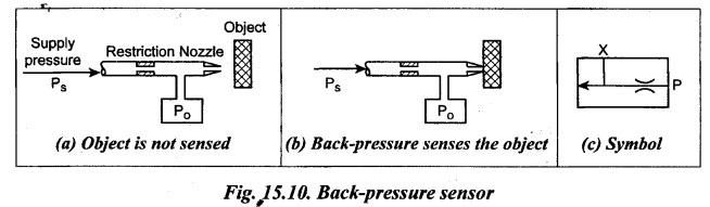
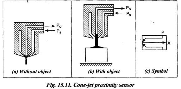
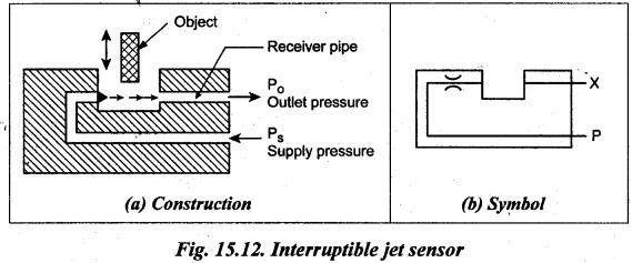
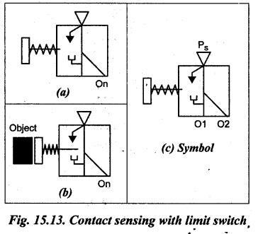
FLUID SENSORS • Fluid sensor is a device that senses a change in some parameter and as a result causes a related change in another parameter that can be recognized and interpreted. • Various types of fluid sensors are used in machine tools and other systems to transmit and receive signals so as to control the actuator speed, position, and pressure. The four important types of fluid sensors relative to fluid power systems are : 1. Back-pressure sensor, 2. Cone-jet proximity sensor, 3. Interruptible-jet sensor, and 4. Contact sensing. Now we shall discuss the construction and operation of the abovesaid fluid sensors in the following sections. • The term 'logic' may be defined as the science that deals with the canons and criteria of validity in thought and demonstration. It is the science of the formal principles of reasoning. The back-pressure sensor works on the principle that the fluid when passed through a nozzle or a restricted passage always has a pressure difference. 1. Construction The construction and operation of a typical back-pressure sensor is illustrated in Fig.15.10. 2. Operation In this sensor, continuity of fluid flow through the nozzle is disrupted by advancing mechanical objects, which creates a back pressure. This back pressure signals (i.e., senses) the presence of the object. As shown in Fig.15.10(a), when the nozzle is not blocked, then the difference between inlet pressure (Ps) and outlet pressure (P) does not change. But when the object is brought near the outlet of the nozzle [Fig.15.10(b)], this induces the back pressure. Now there will be a pressure difference between Ps and Po. This helps in the identification of the object in the path. 3. Symbol Fig.15.10(c) shows the graphic symbol for the back-pressure sensor. A proximity sensor can detect the objects at comparatively greater distance than is possible with a back-pressure sensor. In fact, it can sense gaps 10 times larger than the back- pressure sensor for an equivalent amount of flow consumption. 1. Construction The construction and operation of a typical cone-jet proximity sensor is illustrated in Fig.15.11. This sensor uses an annular nozzle that surrounds a sensing hole. 2. Operation When the sensor supply pressure (P ̧) is supplied, a conical jet forms at the tip of the nozzle. This conical jet encloses a low-pressure bubble within the flow cone, as shown in Fig.15.11(a). Now the pressure at the sensing opening (P) into the base of the cone is normally slightly below the atmospheric pressure. When an object is brought near the flow cone as shown in Fig.15.11(b), a portion of supply jet is reflected from the object into the low pressure bubble region. This increases the output pressure (Po). This increased output pressure permits the switching of the control element. 3. Symbol Fig.15.11(c) shows a graphic symbol of a proximity sensor. 4. Limitations The proximity type sensors have the following drawbacks : 1. Relatively more air consumption. 2. Relatively high cost when compared to back-pressure sensors. 3. Output pressure obtained is very low, therefore the signal amplification is required. 1. Construction The construction and operation of a typical interruptible jet sensor is illustrated in Fig.15.12. It uses a nozzle to transmit air stream across a gap to`a receiver. 2. Operation When the flow is unobstructed, the air is allowed to flow from Ps to Po uninterrupted. But if a mechanical object blocks the gap, then the air jet is blocked after leaving the nozzle tip and the signal at the receiver end disappears. Thus the downstream valve which receives the signal from the outlet end may reverse. 3. Symbol Fig.15.12(b) shows a graphic symbol for the interruptible jet sensor. 4. Advantages The two advantages of using interruptible jet sensors are: 1. Simple in construction and operation. 2. Relatively inexpensive. 5. Limitations The two main drawbacks of interruptible jet sensors are: 1. Only relatively thin objects can be sensed. 2. Like proximity sensors, amplification of signal is required. Because the output pressure obtainable, is very low. Contact sensing is nothing but the sensing of objects by physical contact. It can be achieved by using a device called a limit valve or limit switch. 1. Construction The arrangement and operation of a typical contact sensing with limit switch is illustrated in Figs. 15.13(a) and (b). 2. Operation The operation of this limit switch is very much similar to that of a fluidic OR/NOR gate (discussed in Section 15.4.4), except a mechanical input signal is used rather than a fluid one. When there is no contacting object [Fig.15.13(a)], the output is switched to the normally ON output. When an object contacts the actuator [Fig.15.13(b)], the output switches to the normally OFF output. 3. Symbol Fig.15.13(c) shows a graphic symbol for the limit switch sensor.1. What are Fluid Sensors ?
2. Types of Fluid Sensors
3. Back-Pressure Sensor
4. Cone-Jet Proximity Sensor
5. Interruptible Jet Sensor (or Gap Sensor)
6. Contact Sensing (or Limit Switch)
Hydraulics and Pneumatics: Unit IV: Pneumatic and Electro Pneumatic Systems : Tag: : Pneumatic and Electro Pneumatic Systems - Hydraulics and Pneumatics - Fluid Sensors
Related Topics
Related Subjects

Hydraulics and Pneumatics
ME3492 4th semester Mechanical Dept | 2021 Regulation | 4th Semester Mechanical Dept 2021 Regulation