Manufacturing Processes: Unit III: Bulk Deformation Processes
Flat strip rolling
In rolling plates and sheet with high width-to-thickness ratios, the width of the material remains essentially constant during rolling process.
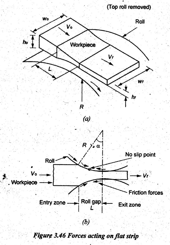
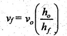
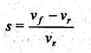
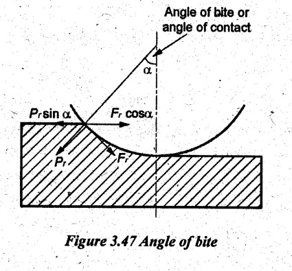
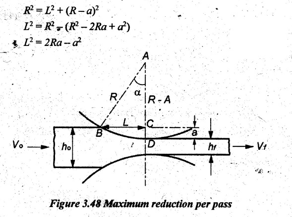
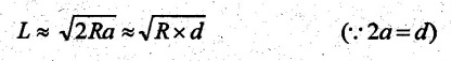
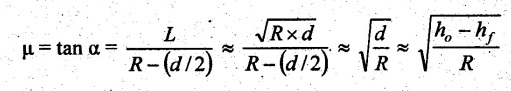
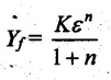
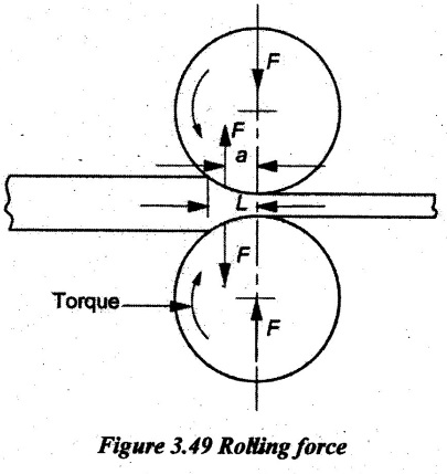
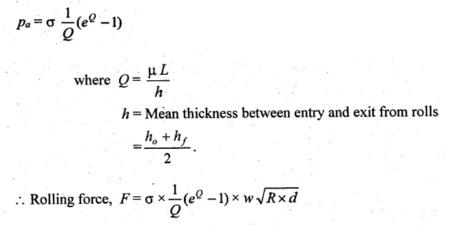
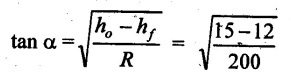
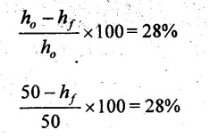
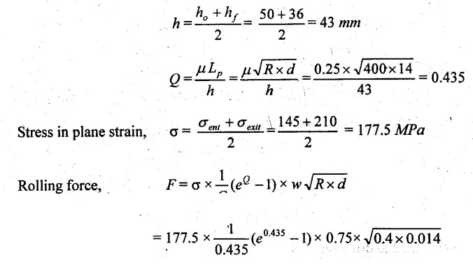
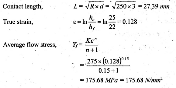
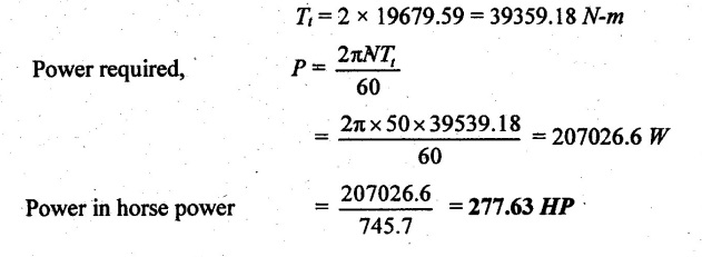
FLAT STRIP ROLLING Flat strip rolling is illustrated in Figure 3.45. It involves the rolling of slabs, strips, sheets and plates of rectangular cross section in which the width is greater than the thickness. In flat rolling, the work is squeezed between two rolls so that its thickness is reduced. In rolling plates and sheet with high width-to-thickness ratios, the width of the material remains essentially constant during rolling process. The schematic diagram of flat strip of flat strip rolling is shown in Figure 3.46 (a). The thickness of strip ho is reduced to hf by a pair of rotating mills. The reduction in amount is called draft. Draft, d = ho - hf = 2R (1 − cos α) where, ho = Starting thickness in mm hf = Final thickness in mm R = Roll radius in mm. α = Bite angle in degree The angle subtended by the centre of the roll with radial force in rolling operations is called angle of bite or bite angle or angle of contact. Draft is sometimes expressed as a fraction of the starting stock thickness called reduction. Reduction, r = d / ho When a series of rolling operations are used, reduction is taken as the sum of the drafts divided by the original thickness. In addition to thickness reduction, rolling usually increases work width. It is called spreading. For calculating the rolling force, the width is taken as the average width. The spreading can be prevented by using vertical rolls. For low.width-to-thickness ratios and low coefficients of friction, the volume of metal exiting the rolls equals the volume entering. howoLo = hfwfLf where ho and hf are the starting and final thicknesses in mm wo and wf are the starting and final widths in mm Lo and Lf are the starting and final lengths in mm. Similarly, the volume flow rates of material flow before and after entering the rolls must be the same. So, before and after velocities can be related as follows: howovo = hfwfvf where vo and vf are the entering and exiting velocities of the work in m/s The surface speed of the rolls is vr. The velocity of the strip increases from its entry value of v。 as it moves through the roll gap. The velocity of the strip is highest at the exit from the roll gap and it is denoted as vf. The exit velocity may be given by the following equation: Exit velocity, Neutral point is the point in the arc of contact where the roll velocity and the strip velocity are the same. Because the surface speed of the rigid roll is constant, there is relative sliding between roft and strip along the arc of contact in the roll gap, L. At one point along the contact length (called neutral point or no-slip point), the velocity of the strip is same as the roll. To the left side of this point, the roll moves faster than the strip whereas to the right of this point, the strip moves faster than the roll. Consequently, the frictional forces which oppose motion between two sliding bodies act on the strip. On either side of this point, slipping and friction occur between roll and work. The amount of slip between rolls and work can be measured by means of the forward slip. It is calculated by Forward slip, The rolls pull the material into the roll gap through a net frictional force on the material. Thus, the net frictional force must be to the right of the neutral point. It also means that the frictional force to the left of the neutral point must be higher than the friction force to the right. Although friction is necessary for rolling materials, energy is dissipated in overcoming friction. Hence, Increasing friction also increases the rolling forces and power requirements. Low and controlled friction is induced in rolling through the use of effective lubricants. For the workpiece to enter the throat of the roll, the component of the friction force must be equal to or greater than the horizontal component of the normal force. In Figure 3.47, Fr is a tangential friction force and Pr is radial force. But we know Fr = μ Pr Therefore, μ = tan α If tan α > μ, the workpiece cannot be drawn. If μ = 0, rolling cannot occur. The maximum reduction per pass between rolls can be calculated as follows: From triangle ABC of Figure 3.48, As a is much smaller than R, a2 can be ignored. Then, the above equation can be written as follows: Therefore, roll strip contact length can be calculated by using the following formulae: We know that the coefficient of friction, Therefore, the maximum possible draft or reduction per pass can be written as dmax = μ2 R Coefficient of friction in rolling depends on lubrication, work material and working temperature. In cold rolling, the value is around 0.1; in warm working, a typical value is around 0.2 and in hot rolling, μ is around 0.4. The true strain experienced by the work in rolling is based on before and after stock thicknesses. In equation form, True strain, ε = ln (ho/ hf) The true strain can be used to determine the average flow stress Yf applied to the work material in flat rolling. Average stress, where K is the strength coefficient of the material n is the work-hardening (or strain-hardening) coefficient The minimum number of passes = (a) Roll force: The rolls apply pressure on the flat strip in order to reduce its thickness, resulting in a roll force, F, as shown in Figure 3.49. In actual case, this force acts at an angle to the plane of motion. But in Figure 3.48, it appears as perpendicular to the plane of the strip. Because in practice, the arc of contact is too small compared with the roll radius. So, the roll force is assumed to be perpendicular to the strip without causing significant error in calculations. The roll force in flat rolling can be estimated from the following formula: F = Yƒ L w where L = Roll strip contact length w = Width of the strip Yƒ = Average true stress. In other way, the rolling force (F) for no friction condition is given by the roll pressure (p) times the area of contact between metal and rolls (w Lp). Where the roll pressure (p) is the yield stress (σ) in plane strain when there is no change in the width (w) of the sheet. For a frictionless situation, an estimate of the actual roll force including friction may be made by increasing the calculated force by about 20%. In the normal case of friction situation in plane strain, the average pressure pa can be calculated by using the following formula: The rolling load (F) also increases as the sheet entering the rolls becomes thinner (due to the term eQ). At one point, no further reduction in thickness can be achieved if the deformation resistance of the sheet is greater than roll pressure. Both the rolls in contact with the sheet are subjected to severe elastic deformation. Small-diameter rolls which are properly stiffened against deflection by backup rolls can produce a greater reduction. (b) Torque and Power per roll: The torque in rolling can be estimated by assuming that the roll force (F) is centered on the work as it passes between rolls and it acts with a moment arm of one-half the contact length L. Thus, torque for each roll is given by T = 0.5FL The power required per roll can be estimated by assuming that rolling force (F) acts at the middle of the arc of contact. Thus, in Figure 3.49, a = L/2. Therefore, the total power (for two rolls) in S.I. units can be written as Power = 2πFLN/6000 in kW where F = Rolling force in N N = Speed of the roll in rpm. Problem 3.1 Calculate the bite angle when rolling plate is 15 mm thick using work rolls 400 mm diameter and reducing the thickness by 3 mm. Given data: ho = 15 mm hf = 15 – 3 = 12 mm D = 400 mm ⇒ R = 200 mm Solution: Referring Figure 3.48, Bite angle, α = 6o 58' Ans. Problem 3.2 Determine the maximum possible reduction for cold rolling a 250 mm thick slab when μ = 0.075 and the roll diameter is 500 mm. What is the maximum reduction on the same mill for hot rolling when μ = 0.45? Given data: ho = 250 mm μ = 0.075 for cold rolling D = 500 mm ⇒ R = 250 mm μ = 0.45 for hot rolling Solution: The maximum possible reduction per pass, for cold rolling ⇒ dmax = μ2 R = 0.0752 × 250 = 1.406 mm Ans. for hot rolling ⇒ dmax = μ2 R = 0.452 × 250 = 50.625 mm Ans. Problem 3.3 Calculate the rolling load if the steel sheet is hot rolled 28% from a 50 mm thick slab Calculates using a 800 mm diameter roll. The slab is 750 mm wide. Assume μ = 0.25. The plane-strain flow stress is 145 MPa at entrance and 210 MPa at the exit from the roll gap due to the increasing velocity. Given data: Reduction ratio = 28% ho = 50 mm D = 800 mm ⇒ R = 400 mm w = 750 mm μ = 0.25 σent = 145 MPa σexit = 210 MPa Solution: ⸫ hf = 36 mm Reduction per pass, d = ho - hf = 50 – 36 = 14 mm Mean thickness between entry and exit from the rolls, Rolling force, F = 12.48 MN Ans. Problem 3.4 A 300 mm wide strip 25 mm thick is fed through a rolling mill with two powered rolls each of radius = 250 mm. The work thickness is to be reduced to 22 mm in one pass at a roll speed of 50 rev/min. The work material has a flow curve defined by K = 275 MPa and n = 0.15 and the coefficient of friction between rolls and work is assumed to be 0.12. Determine if the friction is sufficient to permit the rolling operation to be accomplished. If so, calculate the roll force, torque and horsepower. Given data: Width, w = 300 mm Thickness before rolling, ho = 25 mm Roll radius, R = 250 mm Thickness after rolling, hf = 22 mm Roll speed, N = 50 rev/min K = 275 MPa n = 0.15 Coefficient of friction, μ = 0.12 Solution: Thickness to be reduced, d = ho - hf = 25 – 22 = 3 mm Maximum possible thickness reduction, dmax = μ2R = 0.122 × 250 = 3.6 mm Rolling force, F= w LYf = 300 × 27.39 × 175.68 = 1443562.56 N Ans. Torque required to drive each roll, T = 0.5FL = 0.5 × 1443562.56 × 27.39 × 10-3 = 19679.59 N-m Ans. Total torque required to drive both rolls,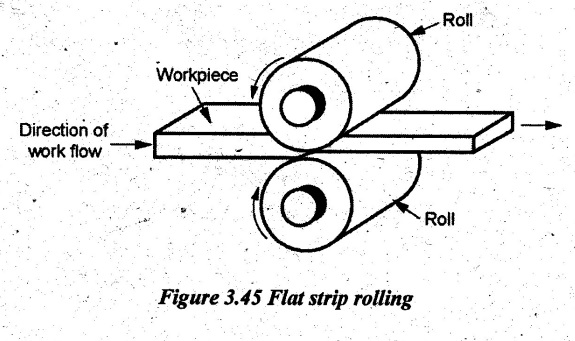
1. Analysis of Flat Rolling
2. Roll Bite Condition

3. Maximum Reduction Per Pass

4. Roll Force, Torque, and Power Requirements

 Therefore, the rolling load F increases with the roll radius √ R depending on the contribution from the friction hill.
5. Solved Problems on Flat Rolling Process

Manufacturing Processes: Unit III: Bulk Deformation Processes : Tag: : - Flat strip rolling
Related Topics
Related Subjects

Manufacturing Processes
ME3393 3rd semester Mechanical Dept | 2021 Regulation | 3rd Semester Mechanical Dept 2021 Regulation