Manufacturing Technology: Unit II: Turning Machines
Feed Mechanism
Turning Machines - Manufacturing Technology
Feed is defined as the movement of the tool relative to the work.
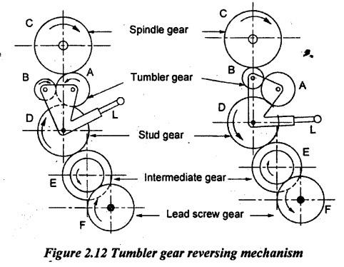
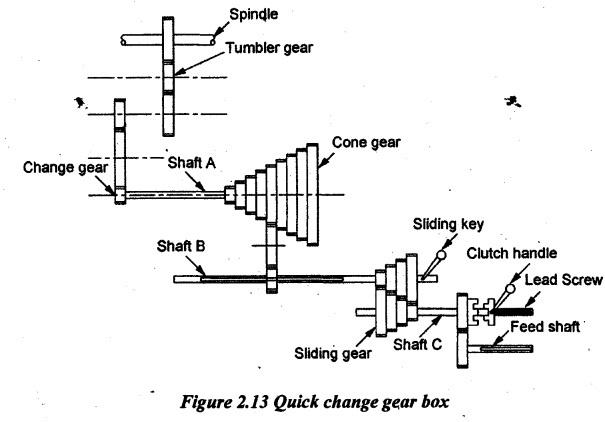
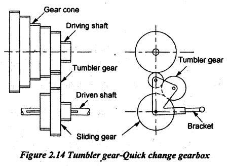
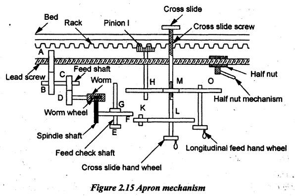
FEED MECHANISM Feed is defined as the movement of the tool relative to the work. The feed mechanism is used to transmit power from the spindle to the carriage. Therefore, it converts the rotary motion of the spindle into linear motion of the carriage. Three types of feeds can be given to the lathe tool. They are longitudinal, cross and angular feeds. Tool movement parallel to the lathe axis is known as longitudinal feed. This feed is achieved by moving the carriage. The movement of tool perpendicular to the lathe axis is called cross feed. It can be achieved by moving the cross slide. The tool movement at an angle to the lathe axis is known as angular feed. It can be achieved by moving a compound slide after swivelling it is at an angle to the lathe axis. The longitudinal and cross feeds can be given either by manually or automatically. For giving automatic feedings, the following feed mechanisms are used. 1. Tumbler gear reversing mechanism 2. Quick-change gearbox 3. Tumbler gear quick-change gearbox 4. Apron mechanism. Tumbler gear mechanism is used to change the direction of the lead screw and feed rod relative to spindle rotation. By engaging the tumbler gear, the carriage can be moved along the lathe axis in either direction during thread cutting or automatic machining. The tumbler gear unit has two pinions (A and B) of same size and it is mounted on a bracket. The bracket is pivoted at a point and it can be moved up and down by a lever L. The bracket may be placed in three positions i.e., upward, downward and neutral. Gear 'C' is a spindle gear attached to the lathe spindle. Gear 'D' is the stud gear. The stud gear is connected to the lead screw gear through a set of intermediate gears. When the lever is shifted upward position, the gear ‘A' is engaged with spindle gear ‘C” and the power is transmitted through C ⇒ A ⇒ D ⇒ E ⇒ F. During this position, the lead screw will rotate in the same direction as the spindle rotates (i.e. both anticlockwise). Now, the carriage moves towards the headstock. When the lever is shifted downward, the gear 'B' is engaged with the spindle gear 'C' and the power is transmitted through C ⇒ B ⇒ A ⇒ D ⇒ E ⇒ F. Hence, the lead screw will rotate in the opposite direction of the spindle i.e., when the spindle rotates in anticlockwise direction, the lead screw will rotate in clockwise direction. Now, the carriage moves towards the tailstock. When the bracket is in neutral position, the engagement of tumbler gears is disconnected with the spindle gear. Hence, there is no power transmission to lead screw. Quick-change gearbox is used to get various power feeds in the lathe. Power from the lathe spindle is transmitted to feed shaft through tumbler gear, change gear train and quick- change gearbox. Shaft A has different sizes of gears and keyed with cone gear. Shaft B has a gear and it receives 9 different speeds from shaft A by the use of sliding gear. The shaft B is connected to the shaft C through 4 cone gears. Therefore, the shaft C can get 9 × 4 = 36 different speeds. The shaft C is connected to the lead screw by a clutch and feed rod by a gear train. The lead screw is used for thread cutting and the feed rod is used for providing automatic feeds. The different speeds for driving shaft are obtained by a tumbler gear and cone gear arrangement. It is simpler than the quick-change gearbox. A tumbler gear and a sliding gear are attached to the bracket as shown in Figure 2.14. The driving shaft has a cone gear made up of different sizes of gears. The sliding gear is keyed to the driven shaft which is connected by the lead screw or feed shaft. The sliding gear can be made to slide and engaged at any desired position. By sliding the sliding gear to various positions and engaging the tumbler gear, the different speeds can be obtained. As already explained in the earlier topic, the apron mechanism is used for transforming the rotary motion of the feed shaft and the lead screw into feed motion of the carriage. There are various designs of this mechanism made by different makers. One type of the mechanism is illustrated in Figure 2.15. Lead screw and feed shaft are getting power from the spindle gear through tumbler gears. Power is transmitted from feed shaft to the worm wheel through gears A, B, C, D and worm. A splined shaft is attached to a worm wheel. The splined shaft is always engaged with the gears F and G which are keyed to the feed check shaft. A knob 'E' is fitted with the feed check shaft. A feed check knob ‘E' can be placed at three positions such as neutral, push-in and pull-out. When the feed check knob ‘E' is in the neutral position as shown in Figure 2.15, the power is not transmitted either to cross feed screw or to the carriage since gears F and G have no connection with gears H and K. Therefore, the hand feed is given as follows. When the longitudinal feed hand wheel rotates, the pinion I will rotate through O, M and H. The pinion I will move on a rack for taking longitudinal feed. For getting the cross feed, the cross slide screw will be rotated by using a cross slide hand wheel. When the feed check knob ‘E' is push-in, the rotating gear G will be engaged with H. Then, the power is transmitted to pinion I. The pinion I will rotate on the rack. So, the automatic longitudinal feed takes place. When the feed check knob 'E' is pulled-out, the rotating gear F will be engaged to K. Hence, the power will be transmitted to cross feed screws through L. It leads to obtain the automatic cross feed. For thread cutting, the half nut is engaged by a half nut lever after putting knob ‘E' in the neutral position. The half nut is firmly attached to the carriage. As the lead screw rotates, the carriage will automatically move along the axis of the lathe. Both longitudinal and cross feeds can be reversed by operating the tumbler gear mechanism.1. Tumbler Gear Reversing Mechanism
2. Quick Change Gearbox
3. Tumbler Gear-Quick Change Gearbox
4. Apron Mechanism
Manufacturing Technology: Unit II: Turning Machines : Tag: : Turning Machines - Manufacturing Technology - Feed Mechanism
Related Topics
Related Subjects

Manufacturing Technology
ME3493 4th semester Mechanical Dept | 2021 Regulation | 4th Semester Mechanical Dept 2021 Regulation