Manufacturing Technology: Unit IV: CNC Machines
Feed drive in CNC Machines
CNC Machines - Manufacturing Technology
Feed drives are used to drive the slide or a table. Figure 4.23 shows various elements of a feed drive.
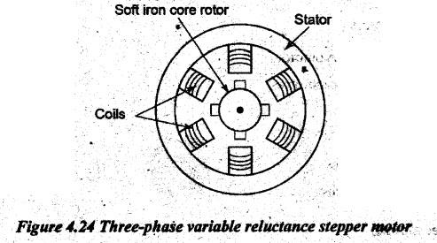
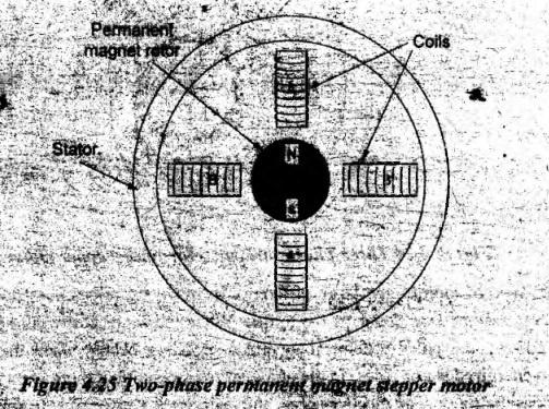
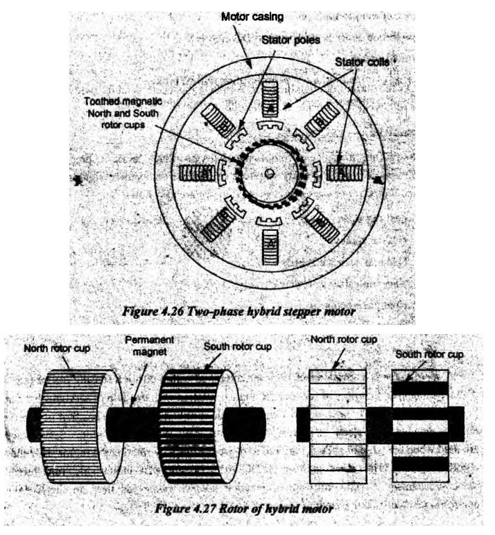
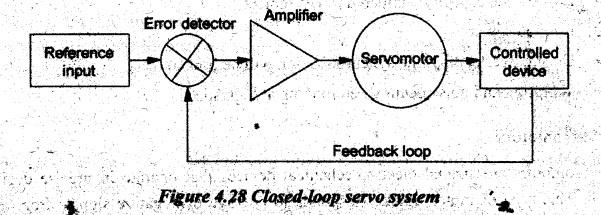
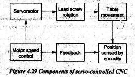
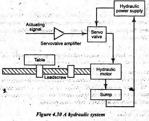
FEED DRIVE IN CNC MACHINES Feed drives are used to drive the slide or a table. Figure 4.23 shows various elements of a feed drive. Feed drive consists of a feed servomotor and e drive, the feed drive motors has some special characteristics such as constant torque and positioning. Also, in contouring operations, several feed drives have to work simultaneously because of the requirement to follow a prescribed path continuously. It requires a sufficient damped servo-system with high band width ie., fast response and matched dynamic characteristics for different axes. The requirements of an ideal feed drive are as follows. 1. Constant torque for overcoming frictional and working force 2. Infinitely variable drive speed with a speed range of at least 1:20,000 3. Maximum speed of around 2000 rpm and at a minimum speed of 0.1 rpm 4. Smooth running of the feed motor 5. Possibility of smallest position increments such as 1-2 μm 6. Four quadrant operation and quick response characteristics 7. Permanent magnet construction 8. Low armature or rotor inertia 9. Low electrical and mechanical time constants 10. Integral mounting feedback devices. Feed drives used in CNC machine tools are as follows. (a) Servomotors (i) DC Servomotors (ii) AC Servomotors (b) Stepper motors (c) Linear motors (d) Hydraulic drives (e) Pneumatic drives. Stepper motor is a special type of DC motor having a permanent magnet or variable reluctance DC motor. It is the simplest device that can be applied to CNC machines since it can convert digital data into actual mechanical displacement. It is an electromechanical device which converts the electrical DC voltage pulses into discrete mechanical movements. The s shaft or spindle of a stepper motor rotates in discrete step increments when electrical command pulses are applied to it in the proper sequence. This characteristic of motor makes it ideally suited for the use with a digitally based control system such as a microcontroller. Stepper motor has the following performance characteristics. • It can rotate in both directions. • It can move in precise angular increments. • It can sustain a holding torque at zero speed, and • It can be controlled with digital circuits. There are three basic types of stepper motors based on the construction. (a) Variable reluctance stepper motor (b) Permanent magnet stepper motor (c) Hybrid stepper motor. (a) Variable reluctance stepper motor: The variable reluctance stepper has a multi-toothed non-magnetic soft iron rotor with a wound stator shown in Figure 4.24. Usually, the number of poles on the rotor is less than the number of poles on the stator. This motor usually has eight stator teeth and six rotor teeth. The number of teeth on the rotor and stator together with the winding configuration and excitation determine the step angle. The teeth of the rotor are so designed that when they are aligned to one phase and they get misaligned to the other. The stator poles have windings and they are switched ON by means of an electronic switching device. The function of the switching device is to switch the control windings in the stator of a stepper motor. In this type of motors, the large difference in magnetic reluctances that exist between direct and quadrature axes develops the torque. When the stator coil windings are energized with DC current, the poles become magnetized. Rotation occurs when the rotor teeth are attracted to energized stator poles. In the non-energized condition, there is no magnetic flux in the air gap, as the stator is an electromagnet and the rotor is a piece of soft iron, hence, there is no detent torque. (b) Permanent magnet stepper motor: The rotor and stator poles of a permanent magnet stepper are not teethed. Instead the rotor is magnetized with alternating north poles, south poles are situated in a straight line parallel to the rotor shaft. The rotor used in the permanent magnet type stepper motor consists of a circular permanent magnet mounted onto the shaft. The stator has four poles shown in Figure 4.25 each pole being geometrically separated by a 90° angle from the adjacent one. In Figure 4.25, AA' and BB' are two phases. Each pole is wound with a field winding. The coils are on opposite pair of poles being in series. The step angle for this motor is 45°. At the end of each step, the rotor assumes the minimum reluctance position that corresponds to the particular magnetic polarity pattern in the stator. It is a relatively low speed, low torque device with large step angles ranging from 45 to 120°. However, smaller step angle can be achieved by either increasing the number of poles in the rotor or increasing the number of phases. It is simple construction and low cost makes it an ideal choice for non-industrial applications such as a line printer print wheel positioner. Applying current to each phase m sequence, the rotor is caused to rotate by adjusting to the changing magnetic fields when the current is given in the situation shown in Figure 4.25, the rotor moves to 45° If the current is switched so that the polarities are reversed, the rotor will move a further 45° in order to line up again. Thus, the rotor rotates by 45° steps by switching ON the current through the coils. Although it is operated at fairly low speed, the PM motor has a relatively high torque characteristic. (c) Hybrid stepper motor: A hybrid stepper is a combination of both permanent magnet and variable reluctance. Hence, it combines the best features of both permanent magnet and variable reluctance type stepper motors. They are constructed with multi-toothed stator poles and a permanent magnet rotor bically, the stator has eight salient poles which are energized by a two-phase winding. The rotor is multi-toothed similar to a variable reluctance motor and it contains an axially magnetized concentric magnet around its shaft shown in Figure 4.26. The magnetic rotor has two cups. One cup is for north poles and second cup is for south poles. The rotor cups are designed so that the north and south poles arrange in alternative manner shown in Figure 4.27. The rotor is made up of a permanent magnet core with two soft iron discs with teeth on the periphery. The number of teeth decides the step angle of the motor. The teeth on the rotor provide an even better path which helps to guide the magnetic flux to preferred locations in the air gap. It further increases the detent, holding and dynamic torque characteristics of the motor when compared to both permanent magnet and variable reluctance types. Standard hybrid motors have 200 rotor teeth and they rotate at 1.8° step angles. Advantages of stepper motors: • Low cost • Ruggedness • Simplicity of construction • Low maintenance • Less likely to stall or slip • Will work in any environment • Excellent start-stop and reversing responses Disadvantages of stepper motors: • Low torque capacity compared to DC motors • Limited speed • During overloading, the synchronization will be broken. • Vibration and noise occur when running at high speed. Servomotors are special electromechanical devices that operate in precise degrees of rotation. This type of motor quickly responds to positive or negative signals from a servo amplifier. The important characteristics of servomotor are as follows. • Fast response • High accuracy • Fast and accurate speed • Very high starting torque • Unattended control • Direction control • Remote operation. A servomotor is a simple electric motor combined with a position sensing device (e.g. digital decoder) and controlled for specific angular rotation with the help of servomechanism. Servomechanism is a typical closed-loop feedback control system. The position of a serva motor is decided by an electrical pulse and its circuitry is placed beside the motor. Servomoto are used when the table or slide is required to move precisely by rotating the motor shaft some specific angles. It is just made up of simple DC, AC or brushless DC motor which runs throug servo mechanism. Servomotors are also called control motors as they are involved controlling a mechanical system. The servo motor is equipped with a position sensor which provides the controller with position and speed information. As a standard, AC servo motors are equipped with resolvers. In combination with the digital servo amplifiers, sincos encoders (absolute encoder, single-turn or multi-turn) and high-resolution incremental encoders may be used as well, in case higher accuracy or dynamics is required. DC servo motors can be equipped with tachogenerators and/or incremental encoders. The servo amplifier (also called amplifier, servo controller, or just controller) controls the current of the motor phases in order to supply the servo motor with exactly the current required for the desired torque and the desired speed. The essential parts of a servo amplifier are the power section and the control loops. Figure 4.28 indicates a block diagram of a typical closed-loop servo system. A reference input is sent to the servo amplifier which controls the speed of the servomotor. A feedback device is mounted on the machine which is either an encoder or resolver. This device changes mechanical motion into electrical signals and is used as a feedback. This feedback is sent to the error detector which compares the actual operation with respect to the reference input. If there is an error, that error is fed directly to the amplifier which will be used to make necessary corrections in control action. In many servo systems, both velocity and position are monitored. Servomotors provide accurate speed, torque, and they have ability of direction control. Figure 4.29 illustrates the components of servo-controlled CNC. A motor speed control is used to control the speed of the servomotor. The servomotor drives the lead screw which in turn drives the slide or table. A position sensing encoder is mounted on the machine which is used as a feedback device. This feedback from encoder is sent to the motor speed control. Servo motors are more robust than stepper motors but they pose a more difficult control problem. They are primarily used in applications where speed, power, noise level as well as velocity and positional accuracy are important. There are mainly two types of servo-motors used. • AC servomotors • DC servomotors. If a DC powered motor is used, then it is called DC servomotor and if it is AC powered motor, then it is called AC servomotor. AC servomotors are generally preferred for low- power use. For high-power use, DC servomotors are preferred because they operate more efficiently than comparable to AC servomotors: (i) DC Servomotors: It is the most common type of feed motors used in CNC machines. The basic operating principle is similar to other electromagnetic motors. The rotors of this kind of motor are designed with long rotor lengths and smaller diameters. They have large size than conventional motors of same power ratings. The principle of operation is based on the rotation of an armature winding in a permanently energized magnetic field. The armature winding is connected to a commutator which is cylinder of insulated copper. segments mounted on the shaft. DC current is passed to the commutator through carbon brushes which are connected to the machine terminals. The change of the motor speed is by varying the armature voltage and the control of motor torque is achieved by controlling the motor's armature current. The DC brush type servomotors are most commonly found in low-end to mid-range CNC machinery. The DC brushless types are typically applied to high-end CNC machinery. (ii) AC Servomotors: This type of motor is basically a two-phase induction motor which is capable of reverse operation. To achieve the dynamic requirements of a servo system, the servomotor must have a small diameter, low inertia and high-resistance rotors. The low inertia allows for fast starts, stops and reverse of direction. The high-resistance rotor provides for almost linear speed/ torque characteristics and accurate control. An AC servomotor is designed with two phases set at right angle to each other. A fixed or reference winding is excited by a fixed voltage source. The control winding is excited by a variable voltage source, usually the servo amplifier. Both sets of windings are usually designed with the same voltage per turns ratio (i.e. with equal voltage applied to each winding, the same magnetic flux will be produced). It allows for maximum control of speed with very little speed drift. In many cases, the design of AC servomotor offers only reasonable efficiency at the sacrifice of high starting torque and smooth speed response Advantages of servomotor: • It provides high output power relative to motor size and weight. • It produces high efficiency. Its efficiency can approach 90% at light loads. • It has high torque to inertia ratio. It can rapidly accelerate loads. • It has "reserve" power. 2-3 times continuous power is for short periods. • It has "reserve" torque. 5-10 times rated torque is for short periods. • Motor stays cool. Current draws proportional to load. • It has high speed torque. • It has audibly quiet at high speeds.de • Resonance and vibration free operation will occur. Disadvantages of servomotor: • Motor develops peak power at higher speeds. Hence, gearing is often required. • Poor motor cooling. Ventilated motors are easily contaminated, • Design is complex. It requires encoder. • Motor can be damaged by sustained overload • Brush wear out limits the life to 2,000 hrs. Service is then required. • Peak torque is limited to a 1% duty cycle • Power supply current is 10 times the average to use peak torque Hydraulic systems are extensively used for driving high-power machine tools and industrial robots since they can deliver large power while being relatively small in size. They can develop much higher maximum angular acceleration than DC motors of the same peak power. They have small time constants and it results the smooth operation of the machine tool slides and robot axes. Hydraulic systems, however, present some problems in terms of mamtenance and leakage of oil from the transmission lines and the system components. The oil must be cleaned and protected against contamination. Other undesirable features are the dynamic lags caused by transmission lines and viscosity variations with oil temperature. In Figure 4.30, hydraulic systems are generally comprised of the following components. 1. A hydraulic power supply 2. A servo valve for each axis of motion 3. A sump 4. A hydraulic motor for each axis of motion. 1. Hydraulic power supply: The hydraulic power supply is a source of high-pressure oil for the hydraulic motor and servo-valve. The main components of the hydraulic power supply system are as follows. 1. A pump is used for supplying the high-pressure oil. The frequently used types are the gear pump, and radial or axial displacement pumps. 2. An electric motor of three-phase induction motor type is used for driving the pump. 3. A fine filter is used to protect the servo system from any dirt or chips. 4. A coarse filter is located at the input of the pump for protecting the latter one against contamination that has entered the oil supply. 5. A check valve eliminates a reverse flow from the accumulator into the pump. 6. A pressure-regulating valve is used for controlling the supply pressure to the servo system. 7. An accumulator is used for storing hydraulic energy and for smoothing the pulsating flow. The accumulator supplies the peak requirements and it is subsequently recharged by the pump. Another function of the accumulator is for smoothening the pulsations caused by the pump and the variations caused by the sudden motions of the valve. The accumulator functions as a capacitor in an electric circuit. 2. Servo valve: The electro-hydraulic servo valve controls the flow of the high-pressure oil to the hydraulic motor. The servo valve receives a voltage-actuating signal and it drives a solenoid device to move the valve spool. The flow rate of oil through the valve is proportional to the velocity of the hydraulic motor. 3. Sump: The used oil is returned to a sump or tank through a special return line. The oil is fed back to the hydraulic power supply and it forms the source of fluid for the latter. 4. Hydraulic motor: The hydraulic motor or actuator is either a hydraulic cylinder for linear motion or a rotary- type motor for angular motion. The hydraulic cylinder is due to the large limited motion. The rotary hydraulic motor is usually used in large power servo systems. It operates at high speeds and it is geared down to the lead screw which drives the table. The pneumatic drives also obey the same principle of hydraulic system, i.e., pressurizing a fluid and delivering it under pressure to where it can do work as in the hydraulic components. It drives use air as working medium which is available in abundant and it is fire proof. They are simple in construction and are cheaper. However, these drives generate low power, have less positioning accuracy and are noisy. Operating principle: In pneumatic power systems, an air compressor is used in place of a hydraulic pump and it is usually located in a remote position within the factory. actuator of either The pr linear of rotary type is used instead of an hydraulic actuator. The compressor will normally be of such a size as to be able to provide a compressed air supply as per the requirement. The high pressure air in CNC machines is around 15 bar and low pressure air is used for various control functions about 6 bar. As a result of the air being compressed, heat, water and oil are introduced into the air supply. Coolers are used to remove the heat and more amount of water is removed by air dryer. The remaining water will require draining at regular points in the system using drain valve. The working principle of a linear motor is similar to a rotary electric motor. It has a rotor and the stator circular magnetic field components are laid down in a straight line. Since the motor moves in a linear fashion, no lead screw is needed to convert the rotary motion into linear. Linear motors can be used in outdoor or dirty environments; however, the electromagnetic drive should be waterproofed and sealed against moisture and corrosion.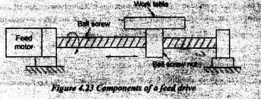
1. Stepper Motors
2. Servomotors
3. Hydraulic Drives
4. Pneumatic Drives
5. Linear Motors
Manufacturing Technology: Unit IV: CNC Machines : Tag: : CNC Machines - Manufacturing Technology - Feed drive in CNC Machines
Related Topics
Related Subjects

Manufacturing Technology
ME3493 4th semester Mechanical Dept | 2021 Regulation | 4th Semester Mechanical Dept 2021 Regulation