Hydraulics and Pneumatics: Unit V: Trouble Shooting and Applications
Failure and troubleshooting of pneumatic system
Trouble Shooting and Applications - Hydraulics and Pneumatics
Pneumatic installation can be categorised into two types:
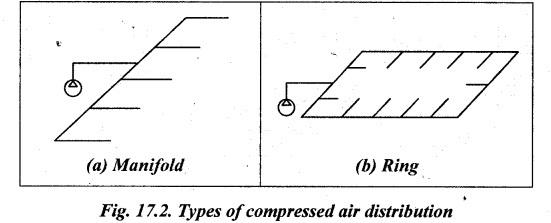
FAILURE AND TROUBLESHOOTING OF PNEUMATIC SYSTEM Pneumatic installation can be categorised into two types: 1. Plant installation: Plant installation is normally for compressed air generation and distribution. It involves distribution of compressed air from compressor to all pneumatic component via systematic piping system. 2. System/machine installation: Machine installation is for connecting all pneumatic actuators to all control valve using pneumatic hose/tube for specific operation. It also includes connection to the main piping system. 1. Pneumatic Piping, Hoses and Connections for Plant Installation • The various end devices in a pneumatic system are linked to the air receiver by pipes, tubes or hoses. • In many schemes the air supply is installed as a fixed service (similar to an electrical ring main) allowing future devices to be added as required. • Two types of compressed air distribution are: (i) manifold, and (ii) ring, as shown in Fig.17.2(a) and (b) respectively. • With strategically placed isolation valves, a ring main has the advantage that parts of the ring can be isolated for maintenance, modification or repair without affecting the rest of the system. • Pneumatic systems are vulnerable to moisture and, to provide drainage, the piping should be installed with a slope of about 1% down from the reservoir. A water trap fitted at the lowest point of the system allows condensation to be run off, and all tap offs are taken from the top of the pipe to prevent water collecting in branch lines. • The pipe sizing should be chosen to keep the pressure reasonably constant over the whole system. The pressure drop is dependent on: (i) maximum flow; (ii) working pressure; (iii) length of line; (iv) fittings in the line (e.g., elbows, T-pieces, valves); and (v) the allowable pressure drop. • Pipe suppliers provide tables or nomographs linking pressure drops to pipe length and different pipe diameters. • Pipe fittings are generally specified in terms of an equivalent length of standard pipe (a 90 mm elbow, for example, is equivalent in terms of pressure drop to 1 metre of 90 mm pipe). • If an intermittent large load causes local pressure drops, installation of an additional air receiver by the load can reduce its effect on the rest of the system. • The local receiver is serving a similar role to a smoothing capacitor in an electronic power supply, or an accumulator in a hydraulic circuit. • Connections can be made by welding, threaded connections, flanges or compression tube connectors. 2. System/Machine installation • Flexible tube made from nylon or polyurethane used to distribute compressed air form valves to cylinder. • Flexible tube come in many color and size so that installation for specific system can be easily identified and better for maintenance purpose. • Normally PUSH IN STUD is used for connection/fitting in valve or cylinder. • Machine used in industrial application use several valves and its convenient to mount them on manifolds so that supply and exhaust connection are common to all. • The advantages for manifold design is that it allows valve to be removed without disconnecting the tubing work and also make the trouble shooting and maintenance easier.INSTALLATION OF A PNEUMATIC SYSTEM
Hydraulics and Pneumatics: Unit V: Trouble Shooting and Applications : Tag: : Trouble Shooting and Applications - Hydraulics and Pneumatics - Failure and troubleshooting of pneumatic system
Related Topics
Related Subjects

Hydraulics and Pneumatics
ME3492 4th semester Mechanical Dept | 2021 Regulation | 4th Semester Mechanical Dept 2021 Regulation