Hydraulics and Pneumatics: Unit III: Hydraulic Circuits and Systems
fail-safe circuits
Hydraulic Circuits and Systems - Hydraulics and Pneumatics
Fail-safe circuits are designed to safeguard the operator, the machine, and the workpiece.
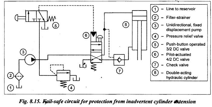
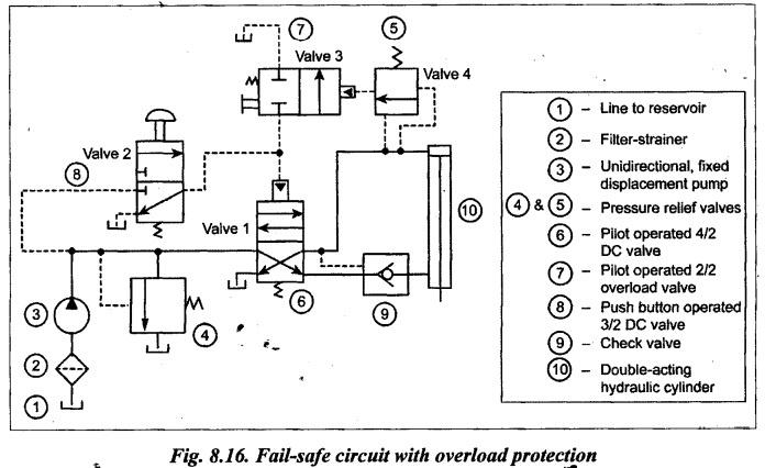
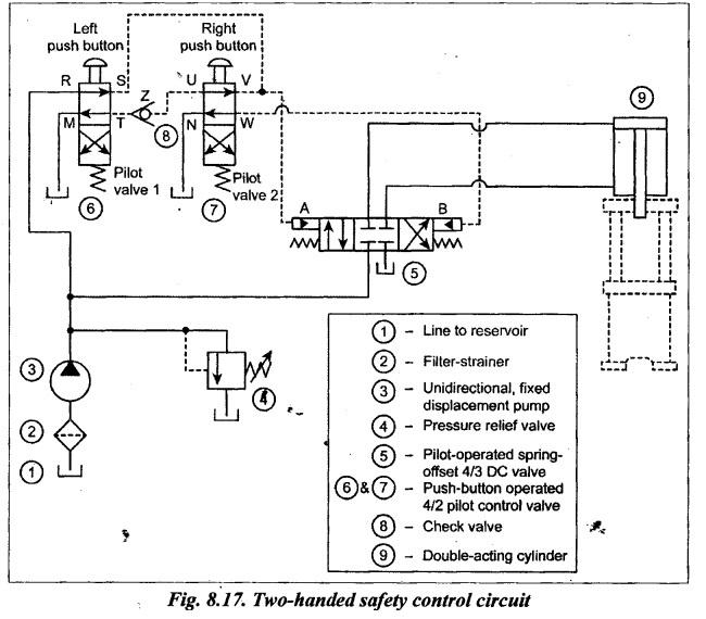
FAIL-SAFE CIRCUITS • Fail-safe circuits are designed to safeguard the operator, the machine, and the workpiece. • These circuits prevent any possible injury to the operator or damage to the machine and the workpiece. • The three important fail-safe circuits are: 1. Protection from inadvertent cylinder extension, 2. Fail-safe system with overload protection, and 3. Two-handed safety overload protection. Now we shall discuss the above circuits one by one. 1. Circuit Fig.8.15 shows a typical fail-safe circuit that is designed to prevent the cylinder from accidentally falling in the event of hydraulic line rupture or pump failure. 2. Operation This circuit allows the upper directional control valve to be placed at a distant location from the machine. The lines connected to the valve are basically for sensing. Flow and pressure (high power lines) go through the bottom DC valve, which acts in a manner similar to relay. The DC valve also provides protection in case someone inadvertently operates the manual override on the pilot actuated directional control valve when the pump is not operating. 1. Circuit The fail-safe circuit that protects the system from overload is shown in Fig.8.16. 2. Operation Push-button 3/2 valve (i.e., valve 2) controls the 4/2 DC valve (i.e., valve 1). When overload valve (i.e., valve 3) is shifted to its left mode, it drains the pilot line of valve 1. If the cylinder experiences excessive resistance during the extension stroke, sequence valvė 4 pilot- actuates overload valve 3. This drains the pilot line of valve 1, causing it to return to its spring-offset mode. If an operator operates push button valve 2, nothing will happen unless overload valve 3 is manually shifted to its blocked port configuration. Thus the system components are protected against overload during its extension stroke. The two-handed safety circuit is designed to protect an operator from accident. 1. Circuit Fig.8.17 illustrates a typical two-handed safety control circuit for safeguarding the operator from injury. This circuit uses a pilot-operated spring-offset 4/3 DC valve and two push buttons. 2. Operation The circuit functions as follows: 1. When the 4/3 DC valve is in its centre position, the oil flow is diverted back to tank through the pressure relief valve. Therefore the cylinder is hydraulically locked. 2. When operator pushes down both left and right push buttons, the oil flows in through port R of pilot valve 1 and out through port S, then through port V of pilot valve 2 and out port U. But check valve Z stops flow. At the same time, the oil also flows to pilot connection A of 4/3 DC valve causing the DC valve to shift to its left mode. When the DC valve is shifted to its left mode, the oil from the pump flows into the blank, end of the cylinder and thus the cylinder extends. Thus the extension of cylinder takes place only when the operator presses both the push buttons. 3. When the operator pushes the right push button only, oil flows in through port R to port S of pilot valve 1, then through port V to port N of pilot valve 2. Thus the oil is drained to the tank through the pilot valve 2. This allows the 4/3 DC valve to return to neutral position; thus the cylinder is hydraulically locked. 4. When the operator pushes the left push button only, oil flows in port R of pilot valve 1 and out port T, then unseats ball in check valve Z, then on to port U of pilot valve 2, and out port V. Oil follows the path of least resistance so it passes in port S of pilot valve 1, out port M and into sump. It does not build up enough pressure to keep pilot pressure on pilot connection A so 4/3. DC valve shifts back to neutral position; thus the cylinder is hydraulically locked. 5. When the operator releases both left and right push buttons, oil flows in port R of pilot valve 1 and out port T, then through check valve Z and into port U of pilot valve 2. Now the oil flows out port W into pilot connection B of 4/3 DC valve shifting its position to right mode. When the 4/3 DC valve is shifted to its right mode, the oil from the pump flows into the rod end of the cylinder and hence the cylinder retracts. Thus the retraction of cylinder takes place only when the operator releases both the push buttons. It may be noted that the operator cannot misuse this safety feature by pressing any one of the push buttons. In order to operate the circuit, the operator has to depress or release both the push buttons of the pilot valves 1 and 2.1. Protection from Inadvertent Cylinder Extension
2. Fail-Safe System With Overload Protection
3. Two Handed Safety Circuit
Hydraulics and Pneumatics: Unit III: Hydraulic Circuits and Systems : Tag: : Hydraulic Circuits and Systems - Hydraulics and Pneumatics - fail-safe circuits
Related Topics
Related Subjects

Hydraulics and Pneumatics
ME3492 4th semester Mechanical Dept | 2021 Regulation | 4th Semester Mechanical Dept 2021 Regulation