Basic Electrical and Electronics Engineering: Unit IV: Digital Electronics
Error Detection and Correction in Binary Code
Digital Electronics
When the digital information in the binary form is transmitted from one circuit or system to another circuit or system an error may occur.
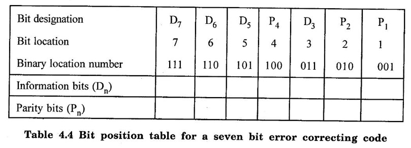
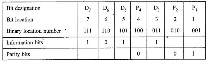
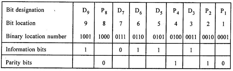
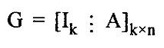
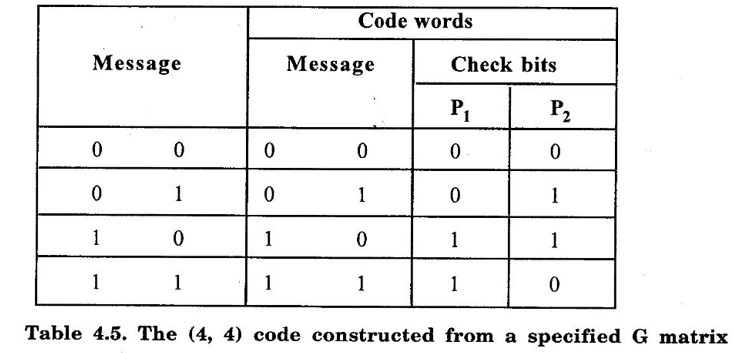
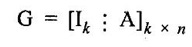
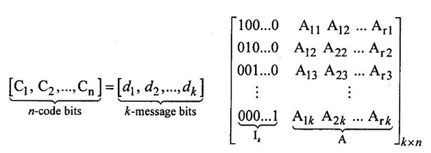
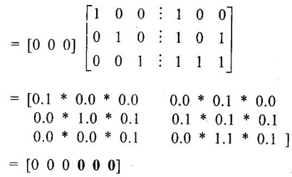
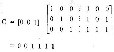
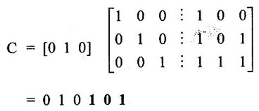
ERROR DETECTION AND CORRECTION When the digital information in the binary form is transmitted from one circuit or system to another circuit or system an error may occur. This means a signal corresponding to 0 may change to 1 or vice-versa due to presence of noise. To maintain the data integrity between transmitter and receiver, extra bit or more than one bit are added in the data. These extra bits allow the detection and some times correction of error in the data. The data alongwith the extra bit/bits forms the code. Codes which allow only error detection are called error detecting codes and codes which allow error detection and correction are called error detecting and correcting codes. A parity bit is used for the purpose of detecting errors during transmission of binary information. A parity bit is an extra bit included with a binary message to make the number of 1s either odd or even. The message, including the parity bit is transmitted and then checked at the receiving end for errors. An error is detected if the checked parity does not correspond with the one transmitted. The circuit that generates the parity bit in the transmitter is called a parity generator and the circuit that checks the parity in the receiver is called a parity checker. In even parity the added parity bit will make the total number of 1s an even amount. In odd parity the added parity bit will make the total number of 1s an odd amount. Table 4.3 shows the 3-bit message with even parity and odd parity Problem 4.16 Write a ASCII code for the decimal digit 9 with an even parity. Place parity bit in the most significant position. Solution : The 7-bit ASCII code for the decimal digit 9 is 0111001. This requires the addition of a 0 in the most significant place to give even parity as shown Added parity bit → 0 0 1 1 1 0 0 1 Problem 4.17 Write a ASCII code for the alphabet 'A' with an odd parity. Place parity bit in the most significant position. Solution : The 7-bit ASCII code for the alphabet 'A' is 1000001. This requires the addition of a 1 in the most significant place to give even parity as shown Added parity bit → 1 1 0 0 0 0 0 1 At the receiving end, message with parity bit is received. Every time it is checked for parity. When parity error is detected, receiver requests for transmitter to re-transmit the message. Problem 4.18 The received code is 1000 0001. Check whether code is correctly received or not if odd parity is used. Solution : The received coe has even parity hence the code is not received correctly. More about parity error detection As a general rule in a digital system where the transmission system is relatively short, it may be assumed that the probability of a single-bit error is small and that of a double-bit error and higher order errors is extremely small. The parity error detection system just described detects any odd number of errors. However, it cannot detect an even number of error because such errors will not destroy the parity of the transmitted group of bits. 3. Block Parity When several binary words are transmitted or received in succession, the resulting collection of bits can be regarded as a block of data, having rows and columns. For example, four eight bit words in succession form an 4 × 8 block. Parity bits can then be assigned to both rows and columns, as shown in fig. 4.1(a). This scheme is known as block parity. It makes it possible to correct any single error occurring in a data word and to detect any two errors in a word. Let us see how we can do this. As shown in the fig. 4.1(b), the third bit in the second data word is in error, having been changed from a 0 to a 1. The number of 1s in the third column is odd, and the number of 1s in the second row is also odd. Therefore, the even parity bits in the third column and second row both detect the error and we know that the third bit from the second word must be changed from a 1 to a 0. Fig. 4.1(c) shows two errors in the first word. Since the total number of 1s is still even, the parity bit in the first row does not detect error. However, the parity bits in the 3rd and 4th columns do detect the error. In this case, we are not able to correct the error because there is no information revealing the row where the errors occurred. Hamming code not only provides the detection of a bit error, but also identities which bit is in error so that it can be corrected. Thus Hamming code is called error detecting and correcting code. The code uses a number of parity bits (dependent on the number of information bits) located at certain positions in the code group. Follows sections describe how Hamming code can be constructed for single error correction. Number of Parity Bits As mentioned earlier, number of parity bits depend on the number of information bits. If the number of information bits is designed x, then the number of parity bits, p is determined by the following relationship : 2P ≥ x + p + 1 ……(1) For example, if we have four information bit, i.e., x = 4, then p is found by trial and error using equation 1. Let p = 2. Then 2P = 22 = 4 and x + p + 1 = 4 + 2 + 1 = 7 Since 2P must be equal to or generator than x + p + 1, the relationship in equation 1 is not satisfied. Hence we have to try with next value of p. Let p = 3. Then 2P = 23 = 8 and x + p + 1 = 4 + 3 + 1 = 8 This value of p satisfies the relationship given is equation (1), and therefore we can say that three parity bits are required to provide single error correction for four information bits. Locations of the Parity Bits in the Code Now we know that how to calculate the number of parity bits required to provide single error correction for given number of information bits. In our example we have four information bits and three parity bits. Therefore, the code is of seven bits. The right-most bit is designed bit 1, the next bit is bit 2, and so on, as shown below : Bit 7, Bit 6, Bit 5, Bit 4, Bit 3, Bit 2, Bit 1 The parity bits are located in the positions that are numbered corresponding to ascending powers of two (1, 2, 4, 8, ...). Therefore, for 7-bit code, locations for parity bits and information bit are as shown below: D7, D6, D5, P4, D3, P2, P1 where symbol Pn designates a particular parity bit, Dn designates a particular information bit, and n is the location number. Assigning Values to Parity Bits Now we know the format of the code. Let us see how to determine 1 or 0 value to each parity bit. In Hamming code, each parity bit provides a check on certain other bits in the total code, therefore, we must know the value of these others in order to assign the parity bit value. To do this, we must write the binary number for each decimal location number as shown in the third row of table: Assignment of P1: Looking at the table 4.4 we can see that the binary location number of parity bit P1 has a 1 for its right-most digit. This parity bit checks all bit locations, including itself, that have 1s in the same location in the binary location numbers. Therefore, parity bit P1 checks bit locations 1, 3, 5 and 7 and assigns P1 according to even or odd parity. For even parity Hamming code, it assigns P1 such that bit locations 1, 3, 5 and 7 will have even parity. Assignment of P2 : Looking at the table 4.4 we can see that the binary location number of parity bit P2 has a 1 for its middle bit. This parity bit checks all bit locations, including itself, that have 1s in the middle bit. Therefore, parity bit P2 checks bit locations 2, 3, 6 and 7 and assigns P2 according to even or odd parity. Assignment of P4: Looking at the table 4.4 we can see that the binary location number of parity bit P4 has a 1 for its left-most digit. This parity bit checks all bit locations, including itself, that have 1s in the left-most bit. Therefore, parity bit P4 checks bit locations 4, 5, 6 and 7 and assigns P4 according to even and odd parity. Problem 4.19 Encode the binary word 1011 into seven bit even parity Hamming code. Solution: Step 1: Find the number of parity bits required. Let p = 3, then 2P = 23 = 8 x + p + 1 = 4 + 3 + 1 = 8 Three parity bits are sufficient. ⸫ Total code bits = 4 + 3 = 7 Step 2: Construct a bit location table Step 3: Determine the parity bits For P1 : Bit locations 3, 5, and 7 have three 1s and therefore to have an even parity P1 must be 1. For P2: Bit locations 3, 6, and 7 have two 1s and therefore to have an even parity P2 must be 0. For P3: Bit locations 5, 6, and 7 have two 1s and therefore to have an even parity P4 must be 0. Step 4: Enter the parity bits into the table to form a seven bit Hamming code = 1010101. Problem 4.20 Determine the single error-correcting code for the information code 1 0 1 1 1 for odd parity. Solution : Step 1: Find the number of parity bits required. Let p = 3, then 2P = 23 = 8 x + p +1 = 5 + 3 + 1 = 9 This will not work. Try p = 4, then 2P = 24 = 16 x + p + 1 = 5 + 4 + 1 = 10 Equation (1) is satisfied and hence four bits are sufficient. ⸫ Total code bits = 5 + 4 = 9 Step 2: Construct a bit location table Step 3: Determine the Parity bits For P1 : Bit locations 3, 5, and 9 have three 1s and therefore to have odd parity P1 must be 0. For P2 : Bit locations 3, 6, and 7 have two 1s and therefore to have an odd parity P2 must be 1. For P4 : For P4 Bit locations 5, 6, and 7 have two Is and therefore to have an odd parity P4 must be 1. For P8 : Bit P8 checks bit locations 8 and 9 and must be 0 to have an odd parity. Step 4: Enter the parity bits into the table to form a nine bit Hamming code = 100111110. In the last section we have seen how to construct Hamming code for given number of information bits. Now we will see how to use it to locate and correct an error. To do this, each parity bit, along with its corresponding group of bits must be checked for proper parity. The correct result of individual parity check is marked by O whereas wrong result is marked by 1. After all parity checks, binary word is formed taking resulting bit for P1 as LSB. This word gives bit location where error has occured. If word has all bits 0 then there is no error in the Hamming code. Problem 4.21 Assume that the evẹn parity Hamming code in example (0 1 1 0 0 1 1) is transmitted and that 0100011 is received. The receiver does not know what was transmitted. Determine bit location where error has occurred using received code. Solution : Step 1: Construct the bit location table. Step 2: Check for parity bits For P1 : P1 checks locations 1, 3, 5 and 7. There is one 1 in the group. ⸫ Parity checks for even parity is wrong → 1 (LSB) For P2: P2 checks locations 2, 3, 6 and 7. There are two 1s in the group. ⸫ Parity checks for even parity is correct → 0 For P4 : P4 checks locations 4, 5, 6 and 7. There is one 1 in the group. ⸫ Parity checks for even parity is wrong→ 1 The resultant word is 1 0 1. This says that the bit in the number 5 location is in . error. It is 0 and should be a 1. Therefore, the correct code is 0 1 1 0 0 1 1, which agrees with the transmitted code. Problem 4.22 The Hamming code 1 0 1 1 0 1 1 0 1 is received. Correct it if any errors. There are foud parity bits and odd parity is used. Solution : Step 1: Construct a bit location table Step 2: Check for parity bits For P1: P1 checks locations 1, 3, 5, 7 and 9. There are four 1s in the group. ⸫ Parity checks for odd parity is wrong → 1 (LSB) For P2: P2 checks locations 2, 3, 6 and 7. There are three 1s in the group. ⸫ Parity checks for odd parity is correct → 0 For P4: P4 checks locations 4, 5, 6 and 7. There are three 1s in the group. ⸫ Parity checks for odd parity is correct → 0 For P8: P8 checks locations 8 and 9. There is one 1 in the group. ⸫ Parity checks for odd parity is correct → 0 The resultant word is 0 0 0 1. This says that the bit in the number 1 location is in error. It is 1 and should be a 0. Therefore, the correct code is 1 0 1 1 0 1 1 00. Block codes are not necessarily linear, but general all block codes used in practice are linear. A linear block code consists of k message bits and r check bits. These r check bits are derived from the original k message bits to form a n-bit block code, as shown in the fig. 4.2. The addition of the r check bits introduces redundancy into the code, thus enabling some form of error control. Such a code is designated as an (n, k) code. At the receiving end, the check bits are used to decide the validity of the received message. In this method, matrices are used to encode the massage. Now before going to see generalized equations for matrix encoding we will see the illustration of matrix encoding with the help of example. Let us assume that we have to transmit 2-bit binary codes. So we can only have. four symbols in our word set. Let our message be : "a" = 00, “b” = 01, "c" = 10, “ď" = 11 Now we have to encode these messages by coding matrix. Coding matrix is also called the generation matrix. It has the form where Ik is the identity matrix of order k and A is an arbitrary k × (n − k) sub-matrix. When the arbitrary sub-matrix A has been specified, the (n, k) block code can be defined completely so that an important step in the design of an (n, k) block code is the structure of A. One of the important criterion in the choice of A is that the resulting code should allow the correction of a codeword received in error. As an example of the construction of an (n, k) block code, consider the A sub- matrix (2, 2) as We know that generation matrix is given as Let us see how to find block code for each message. The block code for each message can be given as, C = DG where C = Block code D = Message bits G = Generation matrix Thus to find C we have to do matrix multiplication of D and G. It is important to note that, while doing matrix multiplication we have to follow the rule of MOD 2, i.e., 1 + 1 = 0 Case 1: Message '00'. Case 2 : Message '01'. Case 3 : Message '10'. Case 4 : Message '11'. The above calculations give the block codes for all messages and are listed in table 4.5 1: Construct G matrix as where Ik: Identity matrix of order k. A: Arbitrary matrix 2. Determine all possible combinations of code using C = DG In general for this can be written as Note: We have seen that for matrix multiplication we have to use MOD 2 arithmetic, i.e., 1 + 1 = 0. For multiple additions this can be generalized as Problem 4.23 The generation matrix for a [6, 3] block code is given below Determine all possible code combinations for this code. Solution : Here n = 6 and k = 3. Therefore message code is 3 bit having eight combinations 111). As n = 6, check bits are n - k = 3. Code for message 0 0 0 : We know that, C = DG Similarly we have, Code for message 0 0 1: Code for message 0 1 0 : Code for message 0 1 1: Code for message 1 0 0 : Code for message 1 0 1: Code for message 1 1 0: Code for message 1 1 1: At the receiving end the receiver does not know the transmitted word. However, it knows A matrix used for generation of code words. Its function is to check the message bits using check bit along with it. This can be done with the following procedure. 1. Form the matrix H as where AT: Transpose (interchanging row and columns) of sub-matrix A Ir : Identity matrix of the order of r (r = number of check bits) Matrix H is called parity-check matrix. 2. Now if H RT = 0 Received word is correct i.e., R = C HRT ≠ 0 Error in the received code i.e., R ≠ C where R : Received code RT: Transpose of R Problem 4.24 For a (4, 2) block code received code is 1 0 1 1. If A = Solution : We know that R = [1 0 1 1] Since, HRT = 0, received code is correct. Problem 4.25 For a (4, 2) block code received code is 1010. If A = Solution : Since, HRT ≠ 0, received code is wrong. Problem 4.26 For (6, 3) block code received code is 1 1 0 0 1 0. Iƒ A = Solution : R = [1 1 0 0 1 0] Since HRT ≠ 0, received code is wrong. It is assumed that the coding/decoding system has been designed to correct single error only. In order to correct the codeword we multiply received codeword with transpose of parity-check matrix to get syndrome. Then result of RHT, i.e., syndrome is compared with the row of transpose of parity-check matrix (HT). Matching row number is the number of bit in error. Error bit is then inverted to get the correct code. The procedure is given below: 1. Find S = RHT where R: Received HT : Transpose of T S = [S1, S2, S3, ...] is called syndrome. 2. Match the result, i.e., S with row of HT. The number of row when the match occur gives the number of bit in error. This bit is inverted to correct the error. Problem 4.27 For a (6, 3) block code received code is 1 1 0 1 0 0. If A = Solution : Since HRT ≠ 0, received code is wrong. Let us find S = RHT Refer HT we can see that S, i.e., [1 0 1] matches with second row of HT. Therefore, second bit of received code is in error. By inverting second bit of received code we get, Corrected received code = RC = [1 0 0 1 0 0] This answer can be varied by referring table 4.6 Check-sums and cyclic redundancy checks are used to detect error in the transmission of block of data. Check-sum is formed by adding all the data bytes in the block, ignoring any carries. It is the arithmetic sum of all data bytes. The resulting sum is stored after the data block. When the data is read, it is re-added and the sum is compared with the recorded check-sum. There is not error in the data transmission if both the sum matches; otherwise data has to be re-transmitted. The cyclic redundancy check (CRC) involves dividing the string of data bytes by a constant. Any remainder from this division is written in as 2 CRC bytes, or characters. When the data is read out, these 2 bytes are subtracted from the data string. The result is divided by the original constant. This division gives a zero remainder if the data contains no errors. The CRC method is usually used for error checking of disk storage.1. Introduction
2. Parity Bit


4. Hamming Code
Detecting and Correcting and Error


5. Linear Block Codes

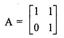
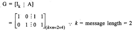
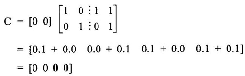
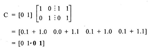
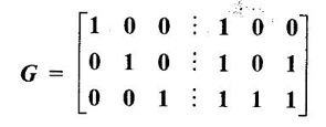
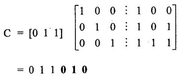
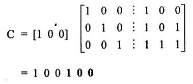
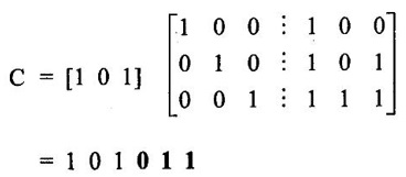
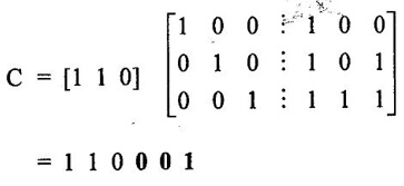
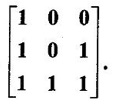
1. Matrix Representation of Linear Block Codes

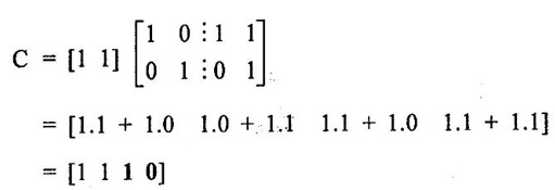
2. Generalized Steps for Construction of Code


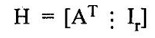
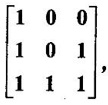
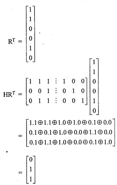
3. Decoding the Received Codewords
 find received code is correct or wrong.
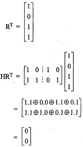
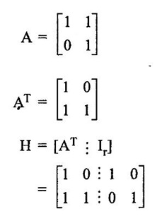
 find received code is correct or wrong.
 find received code is correct or wrong.
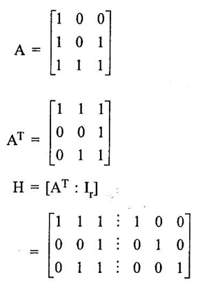
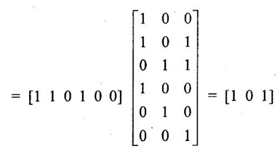
4. Error Correction
 Find the received code is correct or wrong. If wrong correct it.
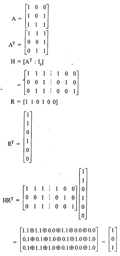
6. Check-sums and Cyclic Redundancy Checks
Basic Electrical and Electronics Engineering: Unit IV: Digital Electronics : Tag: : Digital Electronics - Error Detection and Correction in Binary Code
Related Topics
Related Subjects

Basic Electrical and Electronics Engineering
BE3251 2nd semester Mechanical Dept | 2021 Regulation | 2nd Semester Mechanical Dept 2021 Regulation

Basic Electrical and Electronics Engineering
BE3251 2nd Semester CSE Dept 2021 | Regulation | 2nd Semester CSE Dept 2021 Regulation