Hydraulics and Pneumatics: Unit II: Hydraulic Actuators and Control Components
electrohydraulic servo valve
Hydraulic Actuators and Control Components - Hydraulics and Pneumatics
The growth and popularity of electric control systems has resulted in the development of the electrohydraulic servo valve.
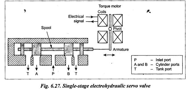
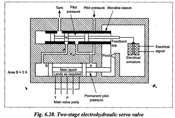
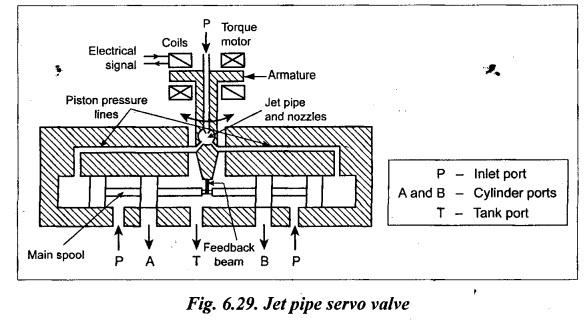
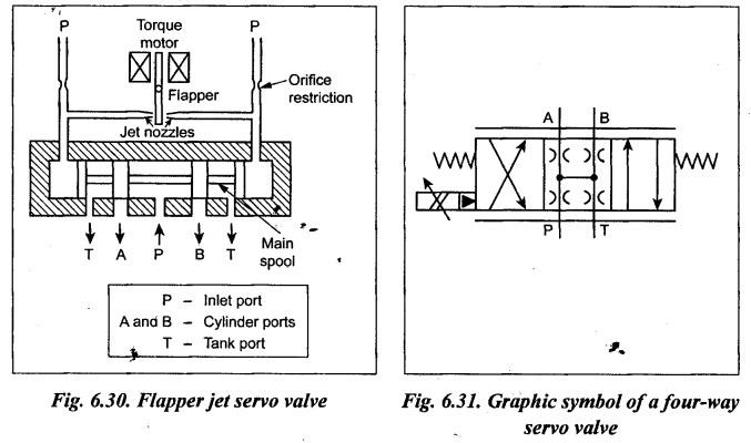
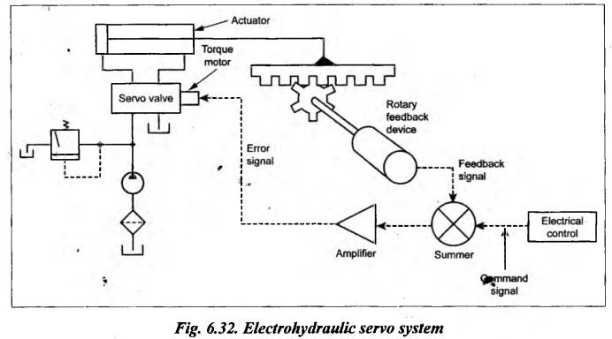
ELECTROHYDRAULIC SERVO VALVE • The growth and popularity of electric control systems has resulted in the development of the electrohydraulic servo valve. • The electrohydraulic servo valve operates due to an electrical signal to its torque motor which positions the spool of the DC valve. In simple terms, if the electrical signal is used as an input (or control) signal to control the hydraulic output, then it is known as electrohydraulic servo valve. • Usually the process control standard current loop signal of 4 to 20 mA is used as an electrical control signal. • Applications: Nowadays, the electrohydraulic servo controls are widely employed in industries, especially in more sophisticated control systems such as on tape-controlled machine tools, high-speed printing presses, press brakes, etc. The electrohydraulic servo systems are used widely in fluid power industries because it offers many advantages when compared to hydromechanical servo systems. Table 6.4 lists some of the main advantages of the electrohydraulic servo systems. Table 6.4. Advantages of electrohydraulic servo systems (over hydromechanical servo systems) 1. The electrohydraulic servo systems can easily achieve the precision remote control of position, force and speed of actuator. 2. They guarantee the higher flexibility of operation. 3. The ensure better control of fluid-compressibility, system-stiffness, and dynamic behaviour of load. 4. They also ensure correct ratio of force and speed that leads to higher energy conversion. 5. They have higher system performance and higher operating efficiency. 6. They enhance easy operator control with failsafe features and higher reliability. 7. They ensures less down time due to less mechanical failures. 8. They achieve higher machine utilisation and less maintenance cost. The four important types of electrohydraulic servo valves are : 1. Single-stage electrohydraulic servo valve, 2. Two-stage electrohydraulic servo valve, 3. Jet pipe electrohydraulic servo valve, and 4. Flapper jet electrohydraulic servo valve. 1. Construction The construction and operation of a typical single-stage electrohydraulic servo valve is illustrated in Fig.6.27. 2. Operation First the electrical signal passes through the coils of a torque motor. The torque motor produces an armature deflection proportional to its input current. Since the armature of the torque motor is connected directly to one end of the valve spool, the spool also shifts by a distance proportional to change in current. 3. Limitation Single-stage servo valves are practical only for limited flows. Because the force required to move the spool at higher flow cannot be achieved. Two-stage servo valves are the most commonly used electrohydraulic servo valves in industries. Because they can handle large flow at high pressure. with a high sensitivity to control changes. 1. Construction The construction and operation of a typical two-stage spool-type servo valve is illustrated in Fig.6.28. The two-stage configuration uses a pilot stage and a main stage. As shown in Fig.6.28, this arrangement consists of a small pilot spool connected directly to the small spool of the pilot valve. The pilot spool moves within a sliding sleeve, mechanically linked to the main spool. The main spool valve is designed in such a way that the effective area of the left hand end of the main spool is twice that of the right hand end. 2. Operation The operation is as follows: 1. The input electrical signal produces an armature deflection by an amount proportional to the command signal. 2. The armature deflection is mechanically transmitted to the pilot spool by means of a stiff connecting wire. The direction of motion of the pilot spool depends on the input electrical signal. 3. Suppose the electrical control signal causes the pilot spool to shift towards left. Now the land X allows the oil flow to the end B of the main spool. Since area B = 2A (Fig.6.28), the main spool shifts towards the right. This in turn pushes the sleeve left. The main valve stops moving when the hole in the pilot sleeve exactly aligns with the land on the pilot spool. 4. A change in electrical signal moving the pilot spool to the right reduces pressure at the left-hand end of the main spool by bleeding fluid back to the tank. This causes the main spool to move left until pilot sleeve and pilot lands are aligned. Thus the main spool valve follows the pilot spool with equal, but opposite movements. 5. The feedback linkage mechanically connects the main spool and pilot spool sleeve. So any movement of the main spool is fed back to the pilot spool sleeve. Thus the two-stage servo valve can provide an extremely accurate flow modulation for fast and precise control of position, velocity and acceleration of the actuator. 1. Construction The construction and operation of a typical jet pipe electrohydraulic servo valve is illustrated in Fig.6.29. This design consists of a jet pipe which is linked mechanically to the main spool. 2. Operation In this design, the pilot pressure is applied to a jet pipe which directs the flow into two pilot lines. The amount of flow in these two pilot lines vary depending on the input electrical control signal. Therefore the control signal diverts the jet flow into two unequal flows. These unequal flows apply unequal pressures at ends of the main spool. Thus the main spool moves towards lesser pressure side. The spool movement stops when the jet pipe is centrally located over the two pilot pipes. This occurs when the main valve spool movement exactly balances the electrical control signal. The feedback to the flapper is provided by internal mechanical leakage or an electrical signal. Flapper jet servo valve is actually the inverse of the jet pipe servo valve. 1. Construction The construction and operation of a typical flapper jet type electrohydraulic servo valve is illustrated in Fig.6.30. 2. Operation In this type, pilot pressure is applied to both ends of the main spool and the sliding spool is actuated by pressure differentials between each end. The pilot pressure lines are linked by two opposing jet orifices against a 'flapper' valve. This flapper valve is attached to the armature. The input electrical signal produces an armature deflection, which in turn deflects the flapper towards one of the jet nozzles. This causes the pressure imbalance. Now the main spool moves until the pressure is balanced on both the ends. It may be noted that the spool moves in proportion to the movement of the flapper valve, which in turn is proportional to the input current. Therefore the volume of fluid passing through the valve is proportional to the input current. 3. Graphic Symbol Fig.6.31 shows the graphic symbol of a four-way servo valve. 1. Construction Fig.6.32 illustrates a circuit that uses a closed-loop electrohydraulic servo control system. This circuit is very much similar to the open loop hydraulic circuit except that a servo valve replaces the flow control and directional valves. 2. Operation In this servo system, a feedback device which is attached to the hydraulic actuator senses the actuator position or speed and transmits a corresponding electrical signal to the servo I valve. This feedback signal is compared with electrical input signal. Suppose the actuator position or speed is not that intended, then the electronic summer will generate an error signal. This error signal is amplified and fed to the torque motor to correct the difference. Therefore electrohydraulic servo valves can provide very accurate control relative to position, speed, pressure and load by incorporating the appropriate feedback devices.1. What are Electrohydraulic Servo Valves?
2. Advantages of Electrohydraulic Servo Systems
3. Types of Electrohydraulic Servo Valves
4. Single-Stage Electrohydraulic Servo Valve
5. Two-Stage Electrohydraulic Servo Valve
6. Jet Pipe Electrohydraulic Servo Valve
7. Flapper Jet Electrohydraulic Servo Valve
8. Electrohydraulic Servo System
Hydraulics and Pneumatics: Unit II: Hydraulic Actuators and Control Components : Tag: : Hydraulic Actuators and Control Components - Hydraulics and Pneumatics - electrohydraulic servo valve
Related Topics
Related Subjects

Hydraulics and Pneumatics
ME3492 4th semester Mechanical Dept | 2021 Regulation | 4th Semester Mechanical Dept 2021 Regulation