Hydraulics and Pneumatics: Unit IV: Pneumatic and Electro Pneumatic Systems
electrical control circuit for regenerative circuit
Pneumatic and Electro Pneumatic Systems - Hydraulics and Pneumatics
A regenerative circuit is commonly used to speed up the extending speed of a double- acting hydraulic cylinder.
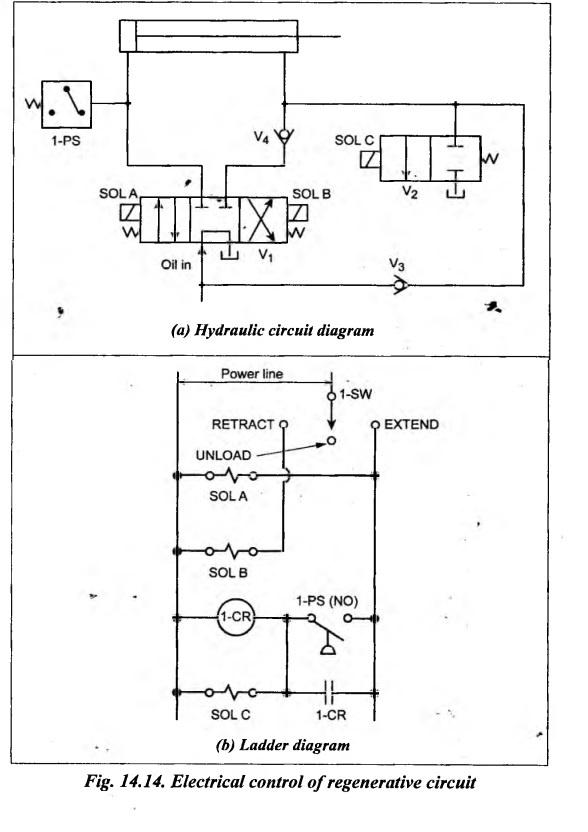
ELECTRICAL CONTROL CIRCUIT FOR REGENERATIVE CIRCUIT A regenerative circuit is commonly used to speed up the extending speed of a double- acting hydraulic cylinder. Fig.14.14 illustrates an electrical control of a regenerative cylinder. Fig.14.14(a) shows the hydraulic circuit of the system and Fig.14.14(b) shows its ladder diagram. The sequence of operation is as follows: Extension stroke 1. First switch 1-SW is manually shifted into the 'EXTEND' position, as shown in Fig.14.14(b). 2. When switch 1-SW is shifted to 'EXTEND' position, the solenoid SOL A is energized. This shifts the 4/3 DC valve V1 to the right mode and it forces the oil to flow into the blind end of the cylinder. Thus the cylinder extends. 3. Now the oil from the rod end of the cylinder passes through check valve V3 to join the incoming oil from the pump. This oil addition facilitates rapid cylinder extension. 4. When oil pressure builds up due to intended loadings on the cylinder, it actuates a normally open pressure switch 1-PS. This energizes both coil 1-CR and SOL C. 5. When the SOL C is energized, the 3/2 DC valve V2 is shifted to the left mode and it directs the oil from the rod end of the cylinder to the oil tank. Thus the cylinder extends slowly when it is loaded. Retraction stroke 6. When switch 1-SW is manually shifted into the 'RETRACT' position [Fig.14.14(b)], the solenoid SOL B is energized. This shifts the 4/3 DC valve V1 to the left mode and it forces the oil to flow into the rod end of the cylinder. Thus the cylinder fully retracts. 7. When the switch 1-SW is manually shifted to the 'UNLOAD' position [Fig.14.14(b)], all the solenoids and the relay coil are de-energized. At this time, the valve V1 is in its spring centered to unload the pump.1. Circuits and Construction
2. Operation
Hydraulics and Pneumatics: Unit IV: Pneumatic and Electro Pneumatic Systems : Tag: : Pneumatic and Electro Pneumatic Systems - Hydraulics and Pneumatics - electrical control circuit for regenerative circuit
Hydraulics and Pneumatics: Unit IV: Pneumatic and Electro Pneumatic Systems
Under Subject

Hydraulics and Pneumatics
ME3492 4th semester Mechanical Dept | 2021 Regulation | 4th Semester Mechanical Dept 2021 Regulation
Related Subjects

Environmental Sciences and Sustainability
GE3451 ESS 4th Semester | 2021 Regulation | 4th Semester EEE Dept 2021 Regulation

Theory of Machines
ME3491 4th semester Mechanical Dept | 2021 Regulation | 4th Semester Mechanical Dept 2021 Regulation
Thermal Engineering
ME3451 4th semester Mechanical Dept | 2021 Regulation | 4th Semester Mechanical Dept 2021 Regulation
Hydraulics and Pneumatics
ME3492 4th semester Mechanical Dept | 2021 Regulation | 4th Semester Mechanical Dept 2021 Regulation

Manufacturing Technology
ME3493 4th semester Mechanical Dept | 2021 Regulation | 4th Semester Mechanical Dept 2021 Regulation
Strength of Materials
CE3491 4th semester Mechanical Dept | 2021 Regulation | 4th Semester Mechanical Dept 2021 Regulation