Manufacturing Technology: Unit III: Reciprocating Machine Tools
Drilling machines
Reciprocating Machine Tools - Manufacturing Technology
Drilling is the process of producing the hole on the workpiece by using a rotating cutter called drill.
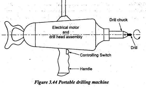
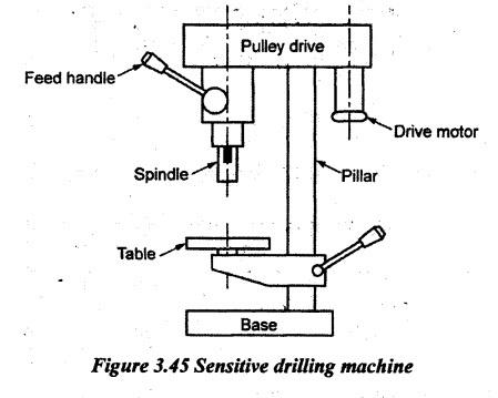
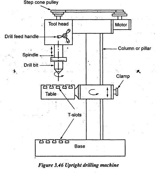
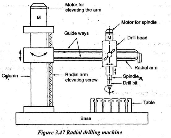
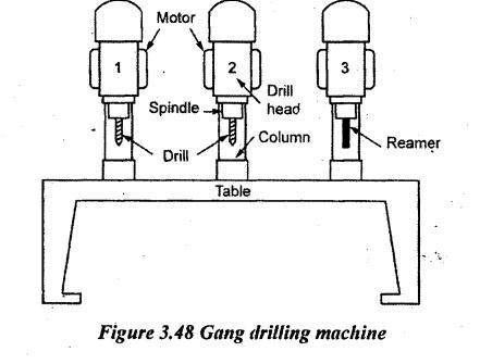
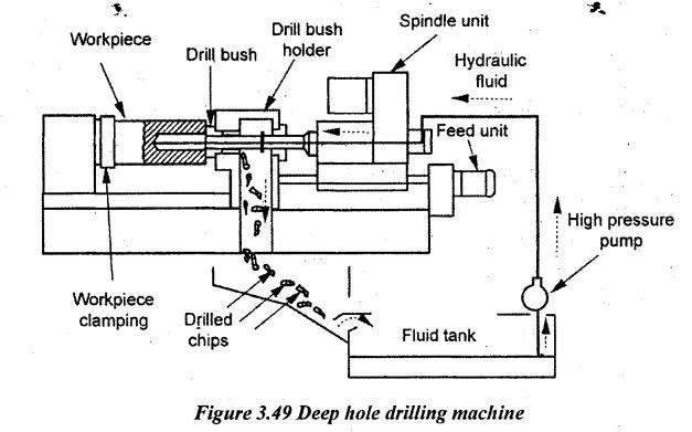
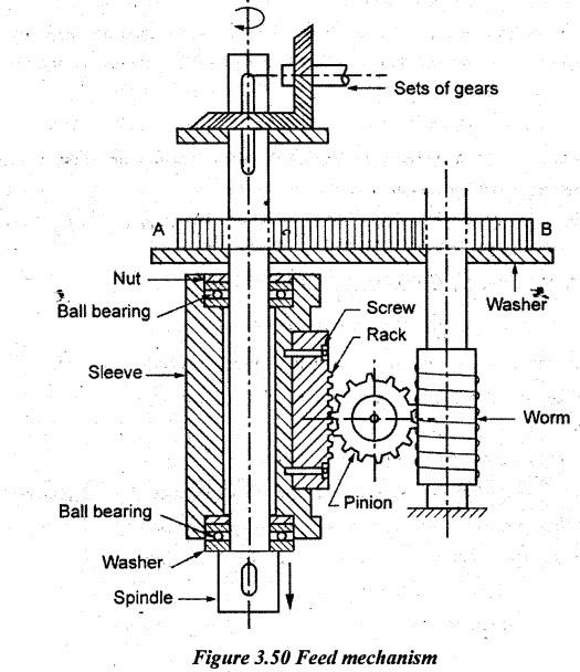
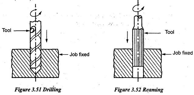
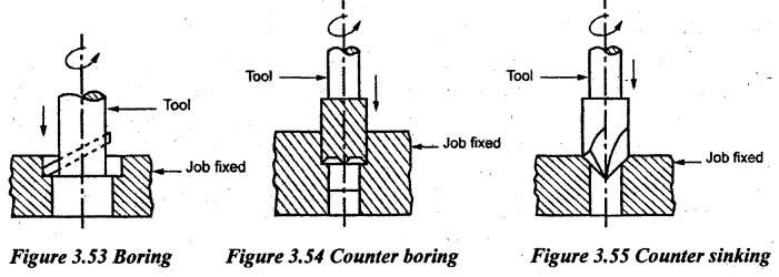
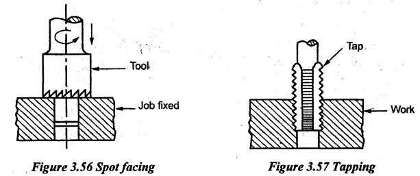
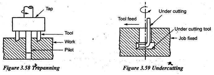
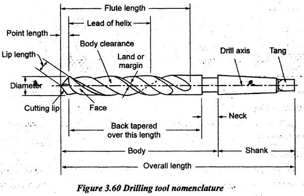
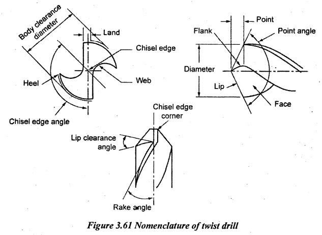
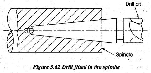
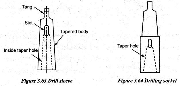
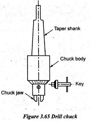
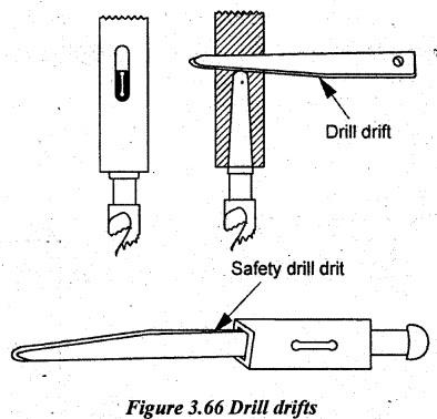
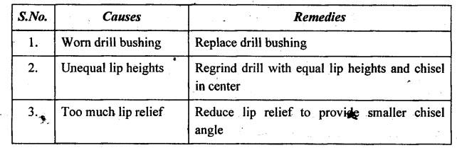
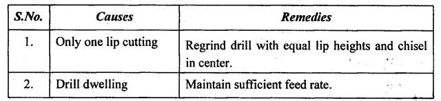
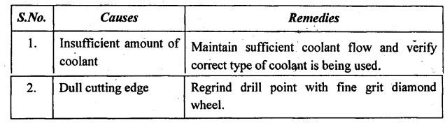
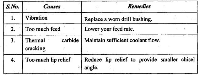
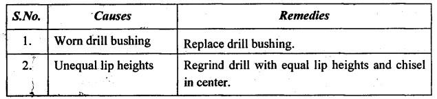
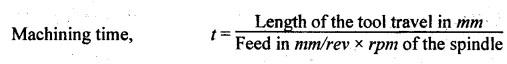
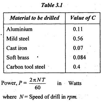
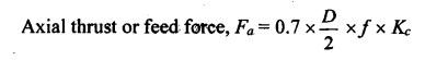
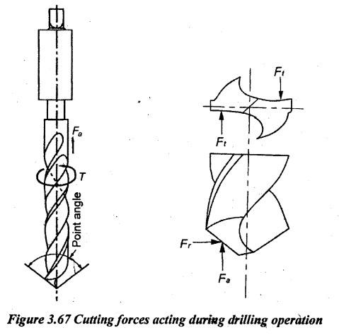
DRILLING MACHINES Drilling is the process of producing the hole on the workpiece by using a rotating cutter called drill. The machine on which the drilling is carried out is called drilling machine. The drilling machine sometimes is called drill press as the machine exerts the vertical pressure to originate a hole. The hole is produced either by giving an axial movement to the rotating drill or axially moving the work against the revolving drill. Though drilling may be done in a lathe or a vertical milling machine, it can conveniently be done economically and quickly in a drilling machine. Drilling machine can also be used for boring, counter-boring, counter- sinking, reaming, tapping and spot facing operations. Drilling machines are used in machine assembly, repair shop, tool room, maintenance work, agricultural machinery etc. The drilling machines are classified as follows. 1. Portable drilling machine 2. Sensitive drilling machine (a) Bench type (b) Floor type. 3. Upright drilling machine (a) Round column type or pillar type (b) Box column type or square section type. 4. Radial drilling machine (a) Plain type (b) Semi-universal type (c) Universal type. 5. Gang drilling machine 6. Multiple spindle drilling machine 7. Automatic drilling machine 8. Deep hole drilling machine. This type of machine is light in weight, compact in a smaller unit and easily handled with respect to the workpiece. It is used for making small holes (up to 18mm diameter) in large workpieces. It is operated by hand power, pneumatic power or electric power. Figure 3.44 shows the schematic diagram of an electrically operated portable drilling machine. Sensitive drilling machines are light-weight, high-speed machines which are generally bench type drilling machines but pillar type machines are also available. It is used for light duty work and drill holes up to 15mm diameter. There is no power feeding arrangement but feeding is purely on hand control of the operator so that the operator can sense the feeding or can control the feeding. Therefore, the machine is called sensitive drilling machine. The main parts of the sensitive drilling machines are base, column, table, spindle and driving mechanism. 1. Column: The column vertically stands on the base. It is a cylindrical post. It supports the table, the spindle head, motor and driving mechanism. 2. Table: The job on which the hole to be produced is mounted on the table. It can vertically be moved along the column and clamped at any position. It can also radially be adjusted around the column. It has T-slots for clamping workpiece or work holding device. 3. Spindle and driving mechanism: It is mounted at the top of the column. It has an electrical drive motor on one side whereas it has the spindle assembly on the other side. The motor drives the spindle through a cone pulley and V-belt arrangement. The belt can be shifted to different sets of pulleys to get different spindle speeds. The spindle is manually fed into the workpiece using a hand lever. The spindle has a Morse taper bore at its bottom end to hold the drill chack. Drill chuck holds the drill bit. Upright drilling machine is a higher capacity version of the sensitive drilling machine. It is a stationary floor mounted drilling machine. It is used for medium sized workpieces and having medium speed. The spindle head and the drive arrangement in this machine are similar to a sensitive drilling machine. But in this case, power-feeding arrangements are available. The main parts of the machine are base, column, worktable and spindle head. 1. Base: It is a supporting member on which all parts of the machine are mounted. It is generally made of cast iron. The top surface of the base is accurately machined. The base has T-slots which are used for mounting large workpiece directly on it. 2. Column: It is a vertical member mounted on the base and it carries the table, spindle and pulley drive mechanism. It should be very strong to take heavy cutting forces. It may be of a round type or box type. In a round type, the column is round in section also named as pillar. The table holding workpiece can be rotated 360° about the column for locating workpiece under the spindle. The drill up to 50 mm diameter is possible in this type. In a box type, the column is square in section, heavier, more strength and rigid than a round type. It can only be raised or lowered by an elevator screw and it will not rotate. The drill diameter more than 50 mm and up to 75 mm is possible by this type. 3. Table: The worktable is attached to the column by means of a clamping screw. The surface of the worktable is accurately machined and it has T-slots on it to hold workpieces. It can vertically move on the column and it can radially be adjusted about the column. As already stated, the table may be rotated about its own axis only in a round column type. 4. Spindle head and drive mechanism: The spindle head is mounted at the top of the vertical column. It is driven by a motor through a belt and step cone drive. The sensitive hand feed is available. A quick traverse hand feed is also available quickly to bring down the drill to the hole location and withdrawn after drilling. The different spindle speeds are obtained by using a step cone pulley arrangement. This type of machine is mounted on the floor and it is more suitable for drilling medium to large and heavy workpieces. The most significant feature of this machine is a radial arm which can swing about a column. The arm can also be moved up and down with respect to the column which can be locked at any desired position as per job size. Figure 3.47 shows the radial drilling machine. The main parts of the machine are base, column, radial arm, drill head, spindle speed and feed mechanism. 1. Base: It is a large rectangular casting. It supports the vertical column and table. The top surface of the base is accurately machined with T-slots to mount the large size workpieces. 2. Column: The column is a cylindrical casting mounted on the base. It supports radial arm, drill head and motor. The column face should accurately be machined to slide the radial arm up and down. An elevating screw is provided on the side of the column to move the radial arm up and down. The elevating screw is rotated by the motor. 3. Radial arm: It is a heavy casting mounted on the column. The drill head is mounted on the radial arm. It has guide ways to move the drill head. The arm can be swiveled around the column. It can be moved up and down by rotating an elevator screw. 4. Drill head: The drill head is mounted on the radial arm. The drill head is equipped with a separate motor. The drill head is manually moved along the arm or with power assistance. The drill head has a spindle which carries the drill bit. 5. Spindle head and feed mechanism: The spindle is driven through a gearbox. The feed can be manual or automatic means. The depth settings for production work with automatic reversal are standard features. Radial drilling machine may be classified with respect to the movements of the radial arm and tool head. The various types of radial drilling machines are: (i) Plain type (ii) Semi-universal type, and (iii) Universal type. (i) Plain type: The following adjustments are available in this type. • Vertical movement of the radial arm with respect to the column. • Circular movement of the radial arm about the column. • Horizontal movement of the tool along the arm ways. (ii) Semi-universal type: In addition to the above three movements as in the case of a plain type, the fourth movement of the tool post can be swung about a horizontal axis perpendicular to the arm. This arrangement permits for drilling a hole inclined at any angle to the horizontal plane. (iii) Universal type: In addition to above four movements as in the case of semi-universal type, the fifth movement permits to rotate (tilt) the radial arm about a horizontal axis. All these movements enable the universal drilling machine to drill on a job at any angle in either horizontal plane or vertical plane or in both the planes. This machine is more suitable for mass production. In this machine, several holes of different sizes can simultaneously be drilled. It has several spindles. They are driven by a single motor by using a set of gears. The centre distance of spindles may be adjusted to any desired length. All spindles holding the drills are fed into the work at the same time. The feed is given either by raising the table or by lowering the spindle head. Drill jigs are sometimes used to guide drills accurately into the work. When a number of single spindles with essential speed and feed are mounted side by side on one base and they have a common worktable known as gang-drilling machine. The number of spindles varies from four to six numbers. The drilling heads of each spindle have individual driving motors as shown in Figure 3.48. Hence, the speed and feeds of the spindles are independently controlled. The gang drilling machine is a mass production type machine. A series of operation can be done one by one. Each spindle of this machine is fixed with respective speed, feed, tool and position of the spindle as per operations required for a production job with the arrangement of job movement by using a suitable jig and fixture. A series of drilling machines are arranged to perform more than one operation at a time in the sequence of successive workstations is called automatic drilling machines. During machining, the workpiece moves automatically to the next station. The automatic movement of the workpiece is obtained through the use of transfer line. The different types of operations such as drilling, reaming, boring, milling etc. can be carried out one after the other in this type drilling machine. Deep hole drilling machines are used when the drill hole depth exceeds the normal drill hole depth. For very deep holes of L/D ratio 6 to even 30, the use of riffle barrels, long spindles, oil holes, bearings and connecting rods are difficult to apply cutting fluids and chip removal. So, the cutting fluids should be pressurised for effective cooling and easy chip removal. Due to deep drill hole, the machine is operated at high speed and low feed. The machine may be a horizontal or vertical type. During drilling, the drill revolves. The center-cut gun drill is specially used in deep hole drilling operations. The drill has a straight flute with single point cutting edge for the whole length of the drill. A hydraulic system is used for forcing oil under high pressure for the whole drill. Some additional features of these machines include the following. 1. Modular accessories allow the high level of flexibility for standard components. 2. This machine covers all major applications spread across numerous industries such as defence, oil and gas fields, automotive, general engineering, heavy engineering, power, nuclear, steel, earth moving equipment. 3. The machine has the facility to handle very long and heavy workpieces. 4. Machines are mainly designed to provide operator safety and ease of operation. 5. The setup changeovers are quicker. 6. CNC controlled process allows the high level of productivity and precision. A drilling machine is specified by the following items. 1. Maximum size of the drill in mm that the machine can be operated. 2. Table size of maximum dimensions of a job can mount on a table in square metre. 3. Maximum spindle travel is in mm. 4. The number of spindle speed and range of spindle speeds are in rpm. 5. The number of automatic spindle feeds or feed ranges is available in mm/rev. 6. Morse taper number of the drill spindle nose is in degrees. 7. Power input of the machine is in HP. 8. Floor space required is in m2. 9. Net weight of the machine is in Tonne. The feed may be controlled by hand or by automatic means. Figure 3.50 shows the automatic feed mechanism. Spindle gets power from the top shaft through two bevel gears. The vertical shaft is splined or feather keyed so that the spindle can rotate as well as they can vertically move up and down for feeding through the bevel gear which remains rotating in a particular position. The spindle rotates within a non-rotating hollow shaft placed on two ball bearings between the hollow shaft and vertical solid shaft as shown in Figure 3.50. The hollow shaft remains in a position along the solid shaft length with the help of a washer at the lower end and a nut at the top end. A rack is mounted on the right side of the hollow shaft. The hollow shaft can move up and down through a pinion meshed with the rack. The pinion gets the power from the top shaft through two spur gears, worm shaft and a worm. Power feed: The gear A rotates with the spindle as the spindle passes through it. Gear B is connected with gear A and gear B also rotates the shaft W. At a suitable point under the shaft, there is a worm which drives a pinion. The pinion is connected to the rack on the hollow shaft fitted over the spindle. The various operations done in a drilling machine are explained as follows. (i) Drilling: Drilling is the operation of cutting a round hole by a rotating tool called drill. Before drilling, the centre of the hole is located on the workpiece. For this, two lines at right angle to each other are drawn. A centre punch is used to mark the centre point of the intersection for two lines. The rotating drill is pressed at the centre point marked on the workpiece to produce the hole. Figure 3.51 shows the drilling operation. Drilling does not produce an accurate hole. The internal surface produced by drilling will be rough. The hole is slightly larger than the size of the drill used due to the vibration of the drill. (ii) Reaming: Reaming is the process of sizing and finishing the already drilled hole. The tool used for reaming is known as a reamer. Reamer is a cylindrical tool having many cutting edges as shown in Figure 3.52. The reamer cannot produce a hole. It simply follows the path of an already drilled hole. It removes less amount of metal. The amount of metal removed in reaming is about 0.375 mm. In reaming, the spindle speed is the half of the drilling process. (iii) Boring: Boring is an operation of enlarging a hole by a single point cutting tool as shown in Figure 3.53. Boring is done where the suitable size drill is not available. If the hole size is very large, it cannot be drilled. Then boring is done to enlarge the hole. By boring, the hole is accurately finished to the required size. The internal surface of a hole in a casting is machined by the boring process. Boring corrects out the roundness of a hole. The cutter is held in a boring bar. The boring bar has a tapped shank to fit into a spindle hole. Boring is a slow process. (iv) Counter boring: The operation of enlarging the end of a hole cylindrically as shown in Figure 3.54 is known as counter boring. (v) Counter sinking: The operation of making a cone-shaped enlargement of the end of a hole is known as countersinking. Figure 3.55 shows the counter sinking operation. (vi) Spot facing: The operation of squaring and smoothing the surface around a hole is known as spot facing. Figure 3.56 illustrates the process of spot facing. (vii) Tapping: Tapping is an operation of cutting internal threads in a hole by using a cutting tool called tap. A tap has cutting edges in the shape of threads as shown in Figure 3.57. When the tap is screwed into the hole, it will remove metal and cut internal threads. The drilled hole will be smaller than the tap size. Tap drill size = 0.8 × Outside diameter of the thread. (viii) Trepanning: The operation of producing a large hole (diameter over 50mm) by removing the metal along the circumference of a hollow cutting tool is known as trepanning. There is a pilot inside the trepanning tool which enters the small drilled hole which is previously made to produce the larger concentric holes as shown in Figure 3.58. It is used for the diameter more than the capacity of a particular machine and where the hole depth is much more in comparison with the normal work. (ix) Undercutting: The operation of enlarging the hole somewhere between its ends as shown in Figure 3.59 is known as undercutting. (x) Grinding: The operation of removing a large amount of stock from the hole drilled in the hardened material to the accuracy up to ± 0.0025 mm by means of a tool named as grinding wheel is known as grinding. (xi) Lapping: The operation of sizing hardened holes and extremely limited in stock removal is known as lapping. (xii) Honing: The operation of finishing relatively large holes in automobile cylinders by means of relatively slow-moving abrasives is known as honing. The different ranges of feed can be obtained by means of a feed gearbox. In a feed gearbox, the different sizes of gears are mounted in two shafts which constantly meshed with each other. A drill or twist drill is a fluted end-cutting tool used for making holes in solid material. It basically consists of two parts. 1. The body consists of the cutting edges, and 2. The shank used for holding purposes. The various parts and angle of the twist drill are shown in Figure 3.60. 1. Body: The body of the twist drill has spiral flutes cut on it. These flutes serve to provide clearance to chips produced at the cutting edge. They also allow the cutting fluid to reach cutting edges. 2. Shank: It is a part that fits into the drill chuck or sleeve. It may be a parallel shank or taper shank. Smaller diameter drills have a straight shank. Morse taper is commonly provided for large diameter tapered drills. The taper shank carries the tang at the end of the shank. It fits into a slot in the machine spindle, sleeve or socket and gives a positive grip. 3. Neck: It is the undercut portion between body and shank. Generally, the size and other details are marked at the neck. 4. Point: It is the cone-shaped end of the drill. The point is shaped to produce lip, face, flank and chisel edge or dead centre. 5. Land or margin: It is a narrow strip. It extends back to the edges of the drill flutes. The size of the drill is measured across the lands at the point end. The land keeps the drill aligned. 6. Web: It is the central portion of a drill situated between roots of flutes and extending from the point towards the shank. 7. Chisel edge: The intersection of flanks forms the chisel edge. It acts as a flat drill. It cuts a small hole in the workpiece at the beginning. Then the cutting edges remove further material to complete the hole. 8. Lip or cutting edge: The cutting edges of a drill are known as lips. Both lips should have equal length, same angle of inclination and correct clearance. 9. Flank: The surface behind the lip following the flute is called flank. 10. Face: This is the portion of the flute surface adjacent to the lip. The chip impinges on it. 11. Heel: The edge which is formed by the intersection of the flute surface and the body clearance is known as heel. 12. Point angle: It is the angle between cutting edges. It is generally 118°. Its value depends on the hardness of the workpiece to be drilled. For harder material, larger angles are used. 13. Rake angle: It is the angle between the face and line parallel to the drill axis. At the periphery of the drill, it is equal to the helix angle. The usual values of rake angle are 30° and 45°. 14. Helix angle: It is the angle between leading edge of the land and axis of the drill. It is also called spiral angle. 15. Lip clearance angle: It is the angle formed by the portion of the flank adjacent to the land and a plane at right angle to the drill axis measured at the periphery of the drill. 16. Chisel edge angle: It is the obtuse angle between chisel edge and lip. Generally, this angle is 120° and 135°. Both taper shank and straight shank drills can be mounted on the drilling machine spindle in a number of ways. They are as follows. 1. Fitting directly in the spindle 2. Using a sleeve 3. Using a socket 4. Using chucks. 1. Fitting directly in the spindle The drill is directly held in the spindle by friction. The spindle of the drilling machine and the shank of the drill have a standard tapered bore. The taper shank of the drill is forced into it. To get a positive drive, (without slipping) the tang of drill fits into a slot at the end of taper bore in the spindle. To remove the drill from the spindle, a tapered wedge called drift is forced into the slotted hole in the spindle as referred in Figure 3.62. 2. Using a Sleeve If the taper shank of the drill is smaller than the taper in the spindle hole, a sleeve is used. The sleeve with the drill is fitted in the hole of the spindle. The sleeve has outside taper surface. It fits into the tapered hole of the spindle. The inside taper of the sleeve can hold the drill or a smaller sleeve. In this sleeve also, there is a tang which is used in the same manner as explained in the previous case. 3. Using a Socket A socket is used to hold the tool into the spindle when the taper shank of the drill is larger than the taper hole of the spindle. The body of the socket has taper hole which is larger than the drill spindle bore. So, a bigger drill can be fitted into the socket. 4. Using Chucks Drill chucks are suitable for holding any smaller size drills, straight shank drills and other tools not having the taper at the holding end. Drill chucks have tapered shanks which fit into the machine spindle. The body of the chuck has three slots at 120o. It is used to house three jaws. The jaws have threads at the back to mesh with a ring nut. The ring nut is attached to a sleeve. The sleeve has bevel teeth on the peripheral face. A key having bevel teeth is used to rotate as shown in Figure 3.65. When the ring nut rotates, the jaws will move in or out. Thus, the ring nut causes the jaws to close or open for holding or releasing the drill. 5. Using Drill Drifts Drill drifts are flat, tapered keys with one rounded edge that are designed to fit into a spindle chuck's slot to force a tapered shank drill loose. The rounded top of the small end of the drill drift is designed to face upward while inserting the drift into the slot. There are two types of drill drifts, the standard type and the safety type shown in Figure 3.66. The standard drift must be inserted into the chuck's slot and then struck with a soft hammer to jar the taper shank drill loose. The drill will fall quickly if not held by the hand and could break or cause injury. The safety drill drift has a sliding hammer weight on the drift itself to allow for a free hand to stay constantly on the drill as it comes loose. (i) Drill breakage: There are mostly two reasons for drill breakage. Deflected breakage is caused by the radial force. So, the drill bit is broken at the end of flute. Twisted breakage is caused by the large torque which means that the drill bit is normally broken at the middle of the flute. (ii) Oversized hole: An oversized hole is caused by too much lip relief, unequal lip heights and a worn drill bushing. The possible remedies to each of the causes are given below: (iii) Short tool life: Short tool life is caused by only one lip on the drill cutting or drill dwelling. The possible remedies to each of the causes are given below: (iv) Rough finish: A rough finish is caused by a dull cutting edge or an insufficient amount of coolant. The possible remedies to each of the causes are given below: (v) Chipped cutting edges or breakage at the outer corners of cutting edges: Chipped cutting edges are caused by any of the following: vibration, too much feed, thermal carbide cracking or too much lip relief. The possible remedies to each of the causes are given below: (vi) Drill walks or drifts: The drill walking is caused by a worn drill bushing or unequal lip heights. Below are possible remedies to each of the causes. 1. Cutting speed: It is the peripheral speed of a point on the surface of the drill in contact with the workpiece. It is usually expressed in m/min. Let D = Diameter of drill in mm N = rpm of drill spindle V = cutting speed in m/min V = π D N / 1000 in m / min The cutting speed mainly depends on the following factors. (i) Type of material to be drilled (ii) Type of drill material (iii) Amount of surface finish required (iv) Type of coolant used (v) Capacity of machine and tool life. 2. Feed: It is the distance of a drill moved into the work for each revolution of the spindle. It is expressed in mm/rev. It may also be expressed in feed per minute. Feed per minute = N× f where N = rpm of the drill spindle f = Feed in mm/rev 3. Depth of cut: Depth of cut is generally one half of the drill diameter. Depth of cut = D/2 where D = Diameter of drill. 4. Machining time: The machining time can be calculated by using the following relation where Length of tool travel = Thickness of metal in mm + 0.3D + Over travel The length of the point of the drill is added with the thickness of the metal because the drill point must clear the metal to complete the hole. It is generally taken as 0.3D if the over travel of the drill is not specifically given. 5. Power of drilling: When a drill cuts, it should overcome the resistance offered by the metal and a twisting effort is necessary to turn it. The effort is called torque on the drill. The torque is depending on the various factors. The relation between torque, diameter of drill and feed is given by the following relation. where T = C × ƒ0.75 × D1.8 T = Torque in N-m f = Feed in mm/rev D = Diameter of drill in mm C = Constant. Depending on the material being drilled, the values of C are taken. Table 3.1 shows the values of C for different materials. To examine the performance of drill bit during drilling process, the measurements of cutting forces are essential. It helps to analyze the: (i) effects of speed and feed on the cutting action of the drill (ii) effects of mechanical properties of work material on the drilling forces and (iii) forces exerted on Drilling machine parts, jigs and fixtures, and the effect of these forces on the dimensional accuracies of the drilled holes. The force R acting on both lips of drill in drilling process may be resolved into three mutually perpendicular force components: axial force (Fa) along the axis of drill, radial force. (Fr) along the radial direction of drill and tangential force (Ft) perpendicular to the force components Fa and Fr. Taking an ideal case of the drill with both lips identical, the radial force components Fr at both lips will get cancelled. Out of the remaining two components, axial components Fa acting on both lips will add to act as an axial thrust F on the drill while the tangential components Ft acting on both lips will form as a torque T opposing the rotation of the drill as shown in Figure 3.67. The following equation can be used to calculate the axial thrust or feed force in drilling. where D = Diameter of drill in mm f = Feed in mm/rev Kc = Specific cutting force in N/m2.1. TYPES OF DRILLING MACHINES
1. Portable Drilling Machine
2. Sensitive Drilling Machine
3. Upright or Pillar Drilling Machine
4. Radial Drilling Machine
5. Multi-spindle Drilling Machine
6. Gang Drilling Machine
7. Automatic Drilling Machine
8. Deep Hole Drilling Machine
2. SIZE OR SPECIFICATION OF DRILLING MACHINE
3. FEED MECHANISM OF DRILLING MACHINE
4. DRILL MACHINE OPERATIONS
5. TWIST DRILL NOMENCLATURE
6. TOOL HOLDING DEVICES FOR DRILLING MACHINES
7. CAUSES OF IMPERFECT DRILLING AND DRILL BREAKAGE
8. DRILLING CALCULATIONS
9. CUTTING FORCES IN DRILLING
Manufacturing Technology: Unit III: Reciprocating Machine Tools : Tag: : Reciprocating Machine Tools - Manufacturing Technology - Drilling machines
Related Topics
Related Subjects

Manufacturing Technology
ME3493 4th semester Mechanical Dept | 2021 Regulation | 4th Semester Mechanical Dept 2021 Regulation