Theory of Machines: Unit I: Kinematics of Mechanisms
displacement diagram for a cam
Kinematics of Mechanisms - Theory of Machines
A typical displacement diagram for a cam is depicted in Fig.3.12.
DISPLACEMENT DIAGRAM FOR A CAM
• The displacement diagram is one in
which the abscissa (i.e., X-axis) represents the angular displacement of cam
and the ordinate (ie., Y-axis) represents the corresponding displacement of the
follower from its initial position.
• A typical displacement diagram for a
cam is depicted in Fig.3.12.
• The displacement diagram consists of
three distinct parts: rise, return, and dwell.
• Dwell is the period during which the
follower remains at rest. Dwell may be between
rise and return, and after return also.
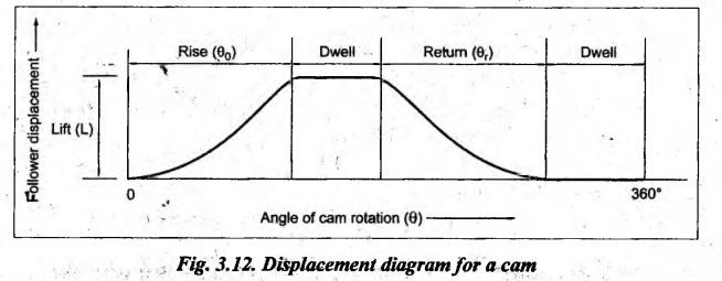
• It may be noted that the points of
inflexion during rise and return portions correspond to the pitch points.
Theory of Machines: Unit I: Kinematics of Mechanisms : Tag: : Kinematics of Mechanisms - Theory of Machines - displacement diagram for a cam
Theory of Machines: Unit I: Kinematics of Mechanisms
Under Subject

Theory of Machines
ME3491 4th semester Mechanical Dept | 2021 Regulation | 4th Semester Mechanical Dept 2021 Regulation
Related Subjects

Environmental Sciences and Sustainability
GE3451 ESS 4th Semester | 2021 Regulation | 4th Semester EEE Dept 2021 Regulation
Theory of Machines
ME3491 4th semester Mechanical Dept | 2021 Regulation | 4th Semester Mechanical Dept 2021 Regulation

Thermal Engineering
ME3451 4th semester Mechanical Dept | 2021 Regulation | 4th Semester Mechanical Dept 2021 Regulation

Hydraulics and Pneumatics
ME3492 4th semester Mechanical Dept | 2021 Regulation | 4th Semester Mechanical Dept 2021 Regulation

Manufacturing Technology
ME3493 4th semester Mechanical Dept | 2021 Regulation | 4th Semester Mechanical Dept 2021 Regulation
Strength of Materials
CE3491 4th semester Mechanical Dept | 2021 Regulation | 4th Semester Mechanical Dept 2021 Regulation