Hydraulics and Pneumatics: Unit II: Hydraulic Actuators and Control Components
direct-acting pressure reducing valve
Construction and Operation, Graphic Symbol
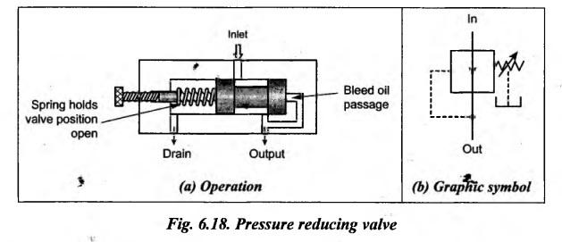
The construction and operation of a direct-acting pressure reducing valve is illustrated in Fig.6.18(a). It has a spring loaded spool to control the downstream (outlet) pressure.
DIRECT-ACTING PRESSURE REDUCING VALVE The construction and operation of a direct-acting pressure reducing valve is illustrated in Fig.6.18(a). It has a spring loaded spool to control the downstream (outlet) pressure. When the main supply pressure is below the valve setting pressure, fluid will flow freely from the inlet to the outlet. It can be noted from Fig.6.18 that an internal connection from the outlet passage transmits the outlet pressure to the spool end opposite the spring. When the downstream (outlet) pressure increases to the valve setting pressure, the spool moves to the left to partly block the outlet port. During this period, only enough flow is passed to the outlet to maintain the preset pressure. If the valve closes completely, leakage could cause the spool pressure to build up. In order to avoid this, a continuous bleed to the tank is permitted to keep the valve slightly open. A separate drain passage is provided to drain this fluid to the tank. Fig.6.18(b) shows a symbolic representation of a pressure reducing valve.1. Construction and Operation
2. Graphic Symbol
Hydraulics and Pneumatics: Unit II: Hydraulic Actuators and Control Components : Tag: : Construction and Operation, Graphic Symbol - direct-acting pressure reducing valve
Related Topics
Related Subjects

Hydraulics and Pneumatics
ME3492 4th semester Mechanical Dept | 2021 Regulation | 4th Semester Mechanical Dept 2021 Regulation