Basic Electrical and Electronics Engineering: Unit V: Measurements and Instrumentation
Digital Storage Oscilloscope
Block Diagram, Modes of Operation, Working Principle
The Digital Storage Oscilloscope eliminates the disadvantages of the analog storage oscilloscope.
DIGITAL STORAGE OSCILLOSCOPE The Digital Storage Oscilloscope eliminates the disadvantages of the analog storage oscilloscope. It replaces the unreliable storage method used in analog storage scopes with the digital storage with the help of memory. The memory can store data as long as required without degradation. It also allows the complex processing of the signal by the high speed digital signal processing circuits. In this digital storage oscilloscope, the waveform to be stored in digitised and then stored in a digital memory. The conventional cathode ray tube is used in this oscilloscope hence the cost is less. The power to be applied to memory is small and can be supplied by small battery. Due to this the stored image can be displayed indefinitely as long as power is supplied to memory. Once the waveform is digitised then it can be analysed in detail. The block diagram of digital storage oscilloscope is shown in the fig. 5.22 The vertical input, after passing through the vertical amplifier, is digitized by an analog to digital converter to create a data set that is stored in the memory. The data set is processed by the microprocessor and then sent to the display. To digitize the analog signal, analog to digital (A/D) converter is used. The output of the vertical amplifier is applied to the A/D converter section. The main requirement of A/D converter in the digital storage oscilloscope is its speed, while in digital voltmeters accuracy and resolution were the main requirements. The digitized output needed only in the binary form and not in BCD. The successive approximation type of A/D converter is most oftenly used in the digital storage oscilloscopes. The digitizing the analog input signal means taking samples at periodic intervals of the input signal. The rate of sampling should be at least twice as fast as the highest frequency present in the input signal, according to sampling theorem. This ensures no loss of information. The sampling rates as high as 100,000 samples per second is used. This requires very fast conversion rate of A/D converter. If a 12-bit converter is used, 0.025% resolution is obtained while if 10-bit A/D converter is used then resolution of 0.1% (1 part in 1024) is obtained. Similarly with 10-bit A/D converter, the frequency response of 25kHZ is obtained. The total digital memory storage capacity is 4096 for a single channel, 2048 for two channels each and 1024 for four channels each. The sampling rate and memory size are selected depending upon the duration and the waveform to be recorded. Once the input signal is samples, the A/D converter digitizes it. The signal is then captured in the memory. Once it is stored in the memory, many manipulations are possible as memory can be read out without being erased. The digital storage oscilloscope has three modes of operation : (i) Role mode (ii) Store mode and (iii) Hold or save mode. Role mode : The fast varying signal is displayed as if it is changing slowly, on the screen. In this mode, the input signal is not triggered at all. The stored is rolled slowly from right to left across the screen. Store Mode : This is most commonly used and called refresh mode. In this mode, the input initiates a trigger circuit. This initiates the memory write cycle. The digital data is transferred to the memory. When the memory is full, the write cycle stops. Using digital to analog converter, the memory data is converted to analog and then played on the screen. When the next trigger occurs the memory is refreshed. Hold or Save Mode : This is called automatic refresh mode. When new sweep signal is generated by time base generator, the old contents get overwritten by new one. If a particular signal is to be stored then by pressing hold or save button, overwriting can be stopped and previously saved signal is locked. Single shot events, such as the waveform of an explosion are transient in nature and very quickly lost. The observer cannot see such events, unless the waveform is photographed or stored. Such events can be stored in memory of digital storage oscilloscope and reading the memory rapidly and repetitively the continuous waveform can be obtained.1. Block Diagram
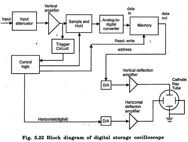 As done in all the oscilloscopes, the input signal is applied to the amplifier and attenuator section. The oscilloscope uses same type of amplifier and attenuator circuitry as used in the conventional oscilloscopes. The attenuated signal is then applied to the vertical amplifier.
2. Modes of Operation
Basic Electrical and Electronics Engineering: Unit V: Measurements and Instrumentation : Tag: : Block Diagram, Modes of Operation, Working Principle - Digital Storage Oscilloscope
Related Topics
Related Subjects

Basic Electrical and Electronics Engineering
BE3251 2nd semester Mechanical Dept | 2021 Regulation | 2nd Semester Mechanical Dept 2021 Regulation

Basic Electrical and Electronics Engineering
BE3251 2nd Semester CSE Dept 2021 | Regulation | 2nd Semester CSE Dept 2021 Regulation