Engineering Graphics: Unit IV (b): Development of Surfaces
Developments of Simple Solids
Engineering Graphics (EG)
Consider a square prism, side of base 'a' and height 'h' as shown in Fig. 16.1. The square prism has 4 rectangular surfaces (a x h) and two bases, top and bottom bases of size (a x a).
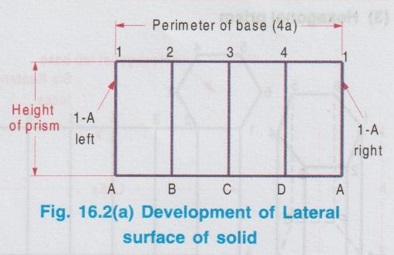
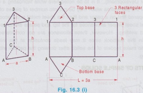
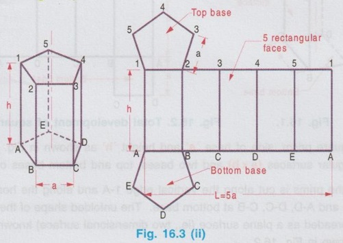
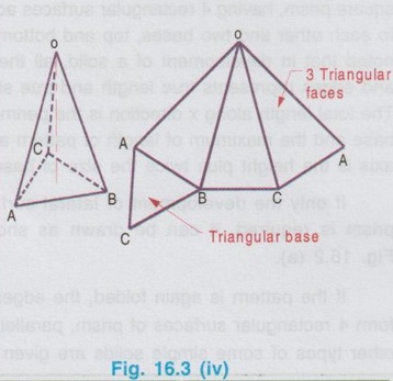
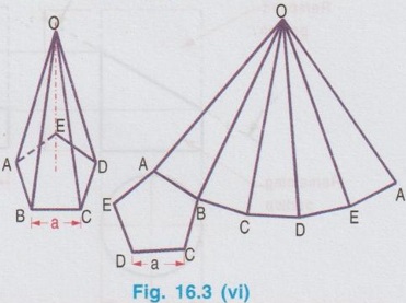
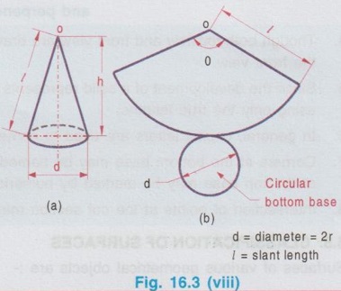
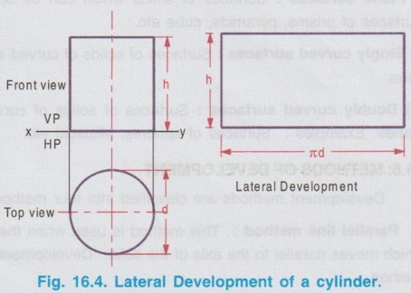
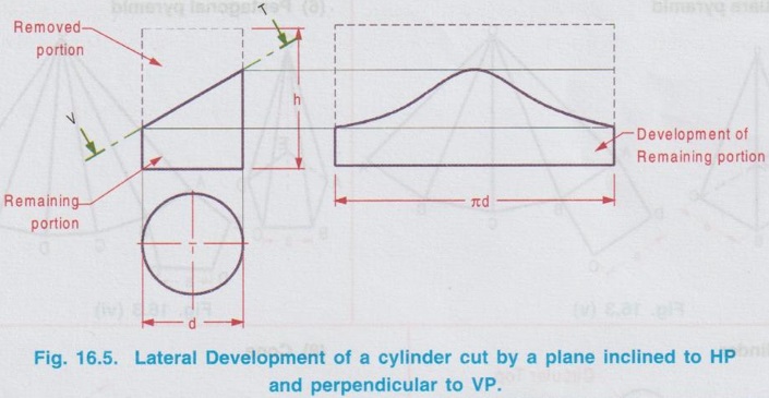
DEVELOPMENTS OF SIMPLE SOLIDS Consider a square prism, side of base 'a' and height 'h' as shown in Fig. 16.1. The square prism has 4 rectangular surfaces (a x h) and two bases, top and bottom bases of size (a x a). Assume that the prims is cut along the vertical edge 1-A and along the horizontal edges 1-4, 4-3, 3-2 at top base and A-D, D-C, C-B at bottom base. The unfolded shape of the prism after cutting these edges and spreaded as a plane surface (ie., two dimensional surface) known as the pattern (or development) is shown in Fig. 16.2. Fig. 16.2. shows the total development of a square prism, having 4 rectangular surfaces adjacent to each other and two bases, top and bottom. It is noted that in development of a solid, all the sides and edges represents true length and true shapes. The total length along x direction is the perimeter of base and the maximum of length of pattern along y axis is the height plus twice the size of base. If only the development of lateral surface of prism is required, it can be drawn as shown in Fig. 16.2 (a). If the pattern is again folded, the edges 1-A (left) and 1-A (right) will coincide each other and form 4 rectangular surfaces of prism, parallel to the axis of prism. Similarly the total development of other types of some simple solids are given below. (1) Development of Triangular (2) Development of Pentagonal prism (3) Hexagonal prism (4) Triangular pyramid (5) Square pyramid (6) Pentagonal pyramid (7) Cylinder (8) Cone Note: 1. Normally the development of lateral surfaces of solid are drawn. 2. While drawing the development of Front view lateral surfaces of solid its projections (Topview and Front view) are drawn first in simple position, keeping the axis of solid perpendicular to HP and parallel to VP. Hence draw the topom view below XY and front view above Top view XY axis and then draw the development of lateral surfaces as shown in fig. 16.4. 3. If the solid is cut by a plane at any angle to the axis of solid, mark the cutting plane in front view and draw the development of lateral surface for the remaining portion of solid after removing the portion of solid removed by cutting plane. Draw the development of full solid using thin lines first and then darken the development of remaining portion of solid as shown below. 4. Though both topview and front view are drawn, usually the development is prepared by refering the front view. 5. Since the development of a solid represents the actual shape of surfaces, development is drawn using only the true lengths. 6. In general, capital letters are used to name the corners of the development. 7. Corners at the bottom base may be named by alphabetic letters A, B, C etc. and the corners at the top base may be marked by numericals 1, 2, 3 etc. 8. Intersection of points at the cut section may be marked as P, Q, R etc.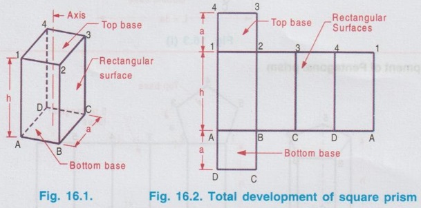


Engineering Graphics: Unit IV (b): Development of Surfaces : Tag: : Engineering Graphics (EG) - Developments of Simple Solids
Related Topics
Related Subjects

Engineering Graphics
GE3251 eg 2nd semester | 2021 Regulation | 2nd Semester Common to all Dept 2021 Regulation