Engineering Graphics: Unit IV (b): Development of Surfaces
Development of Prism
Construction, Steps, Figure diagram, Example Problems | Engineering Graphics (EG)
Note: For uniformity always name the corners in topview in anticlockwise direction. After cutting the vertical edge always unfold in clockwise direction.
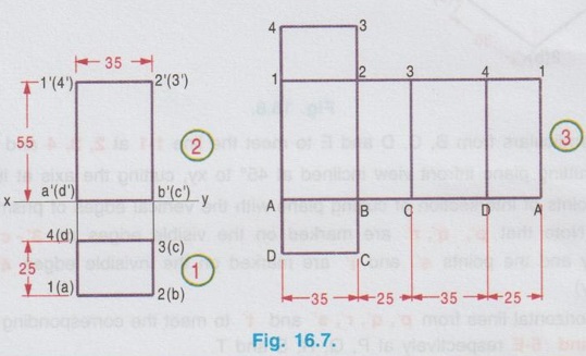
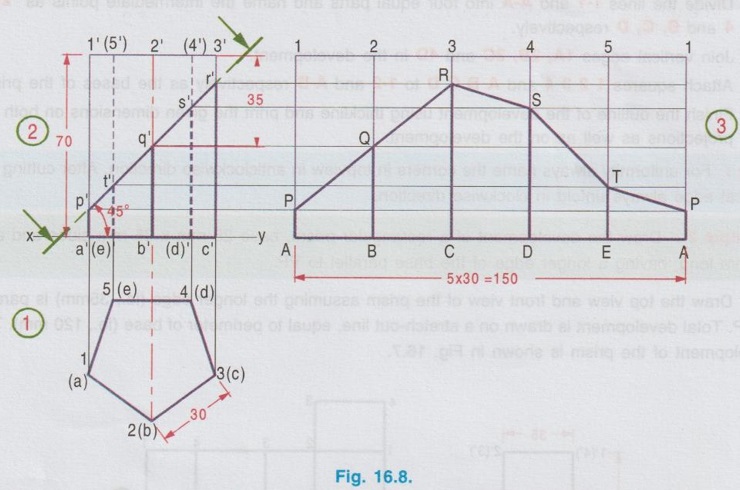
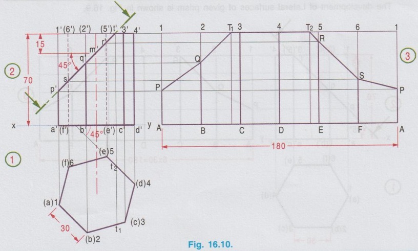
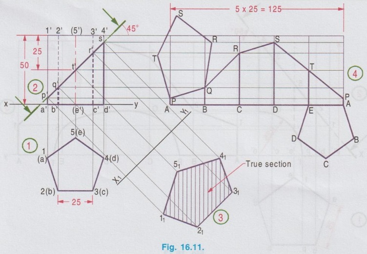
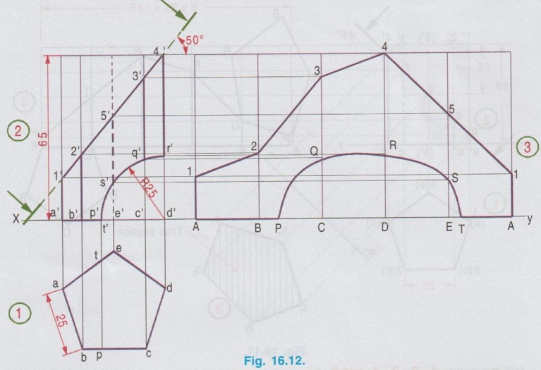
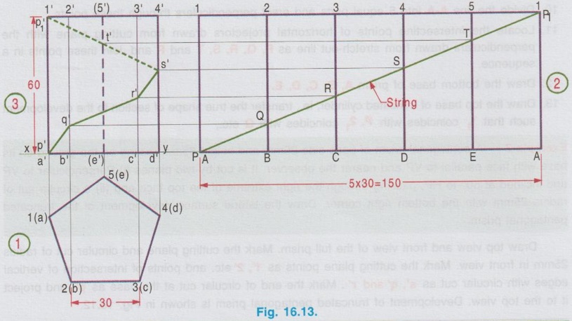
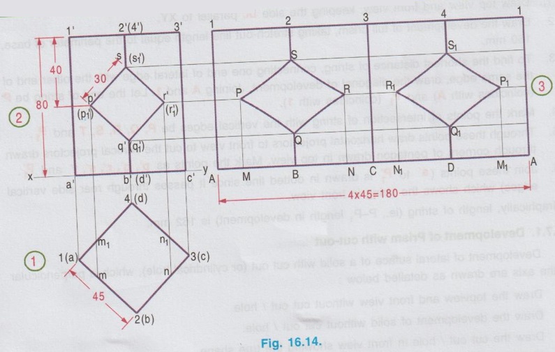
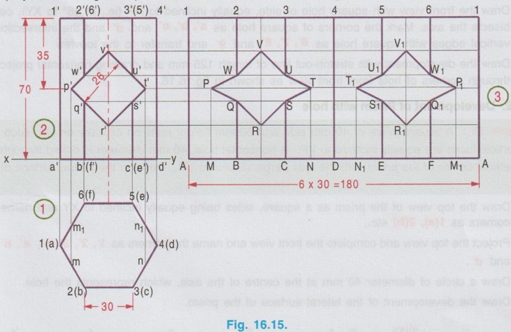
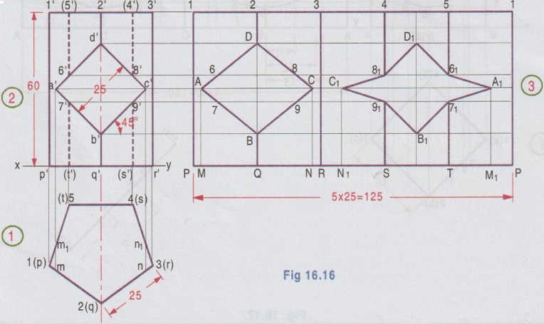
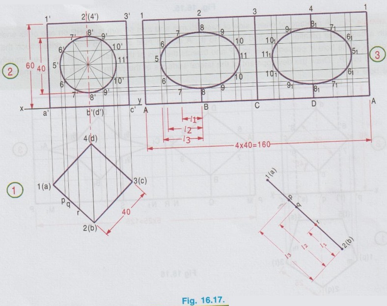
DEVELOPMENT OF PRISM Example 1: Draw the development of a square prism with 35 mm side of base and 65 mm long axis, resting on its base on HP with a rectangular face parallel to VP. Pictorial view of square prism is shown in Fig. 16.6 (i), corners of bottom base named as A, B, C, D and the corners square of top base named as 1, 2, 3, 4. Prism has 4 rectangular faces of 35 x 65 mm each and two square bases 35 × 35 mm each. Assume the prism is cut along the edge 1-A vertically and 2-3, 3-4, 4-1 and B-C, C-D, D-A horizontally and opened out. (Note that, examination point of view pictorial view of object need not be drawn, however it is suggested to draw the pictorial view by freehand sketch and name the corners for clear understanding). The development of prism is shown in Fig. 16.6 (ii). Construction of Development (Fig. 16.6 ii) Step 1 (Top view): Draw a square of size 35 mm as top view and name the corners as 1(a), 2(b), 3(c) and 4(d), showing the hidden corner within the bracket. Step 2 (Front view): Project the topview and complete the front view. Name the corners as 1'(4'), 2′(3'), a'(d') and b'(c'), showing the hidden corners within the bracket. Step 3 (Development) : 1. Draw the stretch out lines 1-1 and A-A from the front view, equal to the perimeter of the base. (ie., 4 × 35 = 140 mm) 2. Divide the lines 1-1 and A-A into four equal parts and name the intermediate points as 2, 3, 4 and B, C, D respectively. 3. Join vertical edges 1A, 2B, 3C and 4D in the development. 4. Attach squares 1 2 3 4 and A B C D to 1-2 and A-B respectively as the bases of the prism. 5. Finish the outline of the development using thickline and print the given dimensions on both the projections as well as on the development. Note: For uniformity always name the corners in topview in anticlockwise direction. After cutting the vertical edge always unfold in clockwise direction. Example 2: Draw the development of a rectangular prism, base 25 mm x 35 mm sides and axis 55 mm long, having a longer edge of the base parallel to VP. Draw the top view and front view of the prism assuming the longer edge (ie., 35mm) is parallel to VP. Total development is drawn on a stretch-out line, equal to perimeter of base (ie., 120 mm). The development of the prism is shown in Fig. 16.7. Example 3: Draw the development of lateral surface of a pentagonal prism, having a base with 30 mm side and a 70 mm long axis, is resting on its base on HP such that one of the rectangular faces is parallel to VP. It is cut by a plane whose V.T is inclined at 45° with the reference line and passes through the mid-point of the axis. Construction: 1. Draw the top view of the prism, keeping one of the edges of base, parallel to XY line. 2. Name the corners as 1(a), 2(b), etc. in anticlockwise direction. 3. Project the top view and complete the front view. Name the corners in front view as 1', 2', 3', 4', 5', a', b', c', d' and e' respectively. 4. Assume the seam line (ie., the edge assumed to cut vertically for unfolding) as 1-A and draw stretch out lines 1-1 and A-A from the front view. 5. Step off AB = length ab, BC= length bc, CD = length cd, DE = length de and EA = length ea, taking the measurements from topview (clearly each has 30 mm length). 6. Erect perpendiculars from B, C, D and E to meet the line 1-1 at 2, 3, 4 and 5 respectively. 7. Draw the cutting plane infront view inclined at 45° to xy, cutting the axis at its mid-point. 8. Mark the points of intersection of cutting plane with the vertical edges of prism as p', q', r', s' and t'. (Note that p', q', r' are marked on the visible edges on 3'-c', 1'-a', 2'-b' respectively and the points s' and t' are marked on the invisible edges 4'-d' and 5'-e' respectively) 9. Draw the horizontal lines from p', q', r', s' and t' to meet the corresponding edges 1-A, 2-B, 3-C, 4-D and 5-E respectively at P, Q, R, S and T. (Note that the points P, Q, R, S and T on the development are not in the order. These points are to be marked on the respective vertical edges refering the front view). 10. Join the points P, Q, R, S, T and P with straight lines. 11. Finish the outline of the development using thick lines and print the given dimensions on both the projections as well as on the development. Example 4: Draw the lateral development of surface of a hexagonal prism side of base 30mm, resting at its base in such a way that two of its rectangular faces are parallel to VP. It is cut by an inclined plane making an angle of 45° with HP and passing through a point 15 mm below the top end of the axis. Take the length of axis as 70 mm. Draw the topview and front view keeping two sides of hexagonal prism parallel to XY. Draw the cutting plane at an angle of 45° with XY meeting the axis in front view at 15mm from top. Draw stretch-out line A-A and 1-1 of length equal to perimeter of hexagonal base (ie., 6 × 30 = 180 mm). The development of Lateral surfaces of given prism is shown in Fig. 16.9. Note : 1. There are two points Q on the development since the point q' cuts both the edges 2'b' and 6'f'. Hence mark the point Q in development on both the vertical edges 2-B and 6-F. But name the points as Q on the front side edge 2-B and Q1 on the rear edge 6-F. 2. The point r' coincides with 3'(5') in front view. Hence mark the point R in development on the edge 3-C and R1 on the edge 5-E. 3. Since the cutting plane does not cut the edge 4'd', no point on the edge 4-D is marked in the development. Example 5: In the above problem, draw the Lateral development if the prism is kept in such a way that one of the sides of base is inclined at 45° to VP. Draw the top view as hexagon, keeping one side of base inclined at 45° to XY and draw front view with cutting plane. The development is shown in Fig. 16.10. Note: 1. Draw the axis in front view and mark the point m', 15 mm from top view and then draw the cutting plane through m' at an angle of 45° with XY. 2. Cutting plane cuts the top base in between the points 5′ and 3′ at t'. Hence project t' to top view to cut at t1 and t2 on edges 2(b) - 3(c) and 4(d) - 5(e) respectively. Measure these distances in top view and mark the same on the development accordingly. Example 6: A pentagonal prism, side of base 25 mm and altitude 50 mm rests on its base on the HP such that an edge of the base is parallel to VP and nearer to the observer. It is cut by a plane inclined at 45° to HP, perpendicular to VP and passing through the centre of the axis. (i) Draw the true shape of section (ii) Draw the development of the complete surfaces of the truncated prism. 1. Draw the topview as a pentagon of side 25 mm, keeping one of the rectangular faces is parallel to XY and nearer to the observer. Name the corners as 1(a), 2(b) etc. 2. Project the top view and complete the front view. Name the corners as 1', 2' etc. and a', b' etc. 3. Draw the cutting plane inclined to XY at an angle of 45° and passing through the midpoint of axis. ie., 25 mm from top base. 4. Name the intersection points as p', q', r', s' and t' cutting the edges 1'a', 2'b' etc. respectively as shown in Fig. True shape of section : 5. Draw another reference axis X1Y1. Draw perpendiculars through the intersection points p', q' etc. perpendicular to the cutting plane. 6. Measure the distance of point 1 (in top view) from XY and measure the same distance on the projector drawn through p' from X1Y1. Let the point be 11. Similarly locate the points 21, 31, 41 and 51 by taking the corresponding distances of 2, 3, 4 and 5 from XY. 7. Join the points 11, 21, 31, 41 and 51 in sequence and hatch the area enclosed which gives the true shape of the section. Total Development: 8. Draw the stretch out line A-A from front view. 9. Draw the horizontal projectors through the intersection points p', q', r', s' and t'. 10. Divide the line A-A into 5 equal parts and erect perpendiculars through these points. 11. Locate the intersecting points of horizontal projectors drawn from cutting plane with the perpendiculars drawn from stretch-out line as P, Q, R, S, T and P and Join these points in a sequence. 12. Draw the bottom base of prism A, B, C, D, E. 13. Draw the top base of truncated cylinder, ie., transfer the true shape of section to the development such that 11 coincides with P, 21, coincides with Q etc., Example 7: A pentagonal prism of base side 25mm and height 65mm resting on the ground on its base with face parallel to VP and nearer the observer. It is cut by two planes (i) Perpendicular to VP and inclined at 50° to HP, passing through the right extreme of the top face and (ii) a circular cut of radius 25mm with the bottom right corner. Draw the lateral surface development of the truncated pentagonal prism. Draw top view and front view of the full prism. Mark the cutting plane and circular cut of radius 25mm in front view. Mark the cutting plane points as 1', 2' etc. and points of intersection of vertical edges with circular cut as s', q' and r'. Mark the end of circular cut at the base as p' and project it to the top view. Development of truncated pentagonal prism is shown in Fig. 16.12. Example 8: A pentagonal prism of base side 30mm and axis height 60mm is resting on the ground with one of its base edges parallel to VP and nearer to the observer. Find graphically the shortest distance of a string, which connects one end of the lateral edge with the other end of the same edge, covering all the lateral surfaces of the solid. Also trace the points on to the development. 1. Draw top view and front view, keeping the side bc parallel to XY. 2. Draw the development of full prism, taking stretch-out line length equal to the perimeter of base, 150 mm. 3. To find the shortest distance of string, connecting one end of lateral edge with the other end of the same edge, draw the diagonal of development, Joining A and 1. Let the end of string be P (coincides with A) and P1 (coincides with 1). 4. Mark the points of intersection of string with the vertical edges be P, Q, R, S, T and P1. 5. Through these points draw horizontal projectors to front view to cut the vertical projectors drawn through corners of pentagon drawn in top view. Mark the points as p', q', r', s', t' and P1'. 6. Join these points (s' to P1' is drawn in dotted line. since it passes through rear side vertical edges) which shows the string in front view. Graphically, length of string (ie., P-P, length in development) is 162 mm. Development of lateral suface of a solid with cut out (or cylindrical hole), which is perpendicular to the axis are drawn as detailed below : ● Draw the topview and front view without cut out / hole. ● Draw the development of solid without cut out / hole. ● Draw the cut out / hole in front view showing the true shape. ● Project the cut out / hole to the top view and name the intersecting points. ● Transfer the corresponding distances of intersecting points to the development and join the points in proper sequence. Note: When a cut out / hole exists in a solid, since the lateral development of solid is prepared, two numbers of cut out / hole to be indicated, one lies on the front face of the solid and the other lies on the rear side of the solid. Example 9: A square prism base of side 45 mm and 80 mm height stands on HP with two of its edges equally inclined to VP. The prism has a square hole of 30 mm side centrally cut right through the prism such that its faces are equally inclined to HP. The axis of the hole is parallel to HP and perpendicular to VP. Draw the development of the lateral surfaces of the prism showing the true shape of the square cut out formed on it. 1. Draw a square as the top view, of side 45 mm, equally inclined to XY and name the corners as 1(a), 2(b), 3(c) and 4(d). 2. Project the top view and complete the front view. Name the corners accordingly. 3. Draw a square hole of side 30 mm fixing its centre at the mid point of axis and keeping two of its faces are equally inclined to HP. 4. Name the corners as p', q', r', s'. (p1', q1', r1', s1', are the corresponding points on the rear side hole). 5. Draw the development of prism from front view without central cut out. 6. Project the central cut from elevation to top view to cut the edges 1(a) - 2(b) and 1(a) - 4(d) at m and m1 and the edges 2(b) - 3(c) and 3(c) - 4(d) at n and n1 respectively. 7. Draw the horizontal projectors from cut out to the development. 8. Measure the distance am from top view on the edge ab and mark the same on development on AB at M. 9. Draw a vertical line through M to meet the horizontal line drawn through p' at the point P. 10. Similarly locate the points Q,R,S in the development and join them in a proper sequence. 11. In the similar way locate the points P1, Q1, R1 and S1 after locating the points M1 and N1 on stretchout line and drawing horizontal projectors from cut out. Note: 1. Corners on cut out in elevation are marked as P'(P1') etc. in which P1' is marked in bracket since it appears on the rear side of prism. 2. In rear side of prism the cut out is marked as R1, Q1, P1, S1 where as the front side of prism is marked as P, Q, R, S in the same order. Example 10: A Hexagonal prism of side of base 24 mm and axis 70 mm is resting on HP on one of its ends with a base edge parallel to VP. A square hole of side 26 mm is drilled such that the axis of the hole is perpendicular to VP and bisects the axis of the prism with all the faces equally inclined to HP. Draw the development of the lateral surfaces of the prism showing the true shape of the hole. 1. Draw the top view as hexagon, keeping one side of edge parallel to VP. Corners in top base are marked as 1, 2, 3 etc., and the corners in bottom base are marked as a, b, c etc. 2. Draw the front view with square hole, centre of square hole bisecting the axis of prism. (ie., 35mm from top). Sides of square hole made equally inclined to HP (ie., at 45° to XY). Name the ends and points of intersection of projectors drawn through all the corners from top view as p', q', r' etc., 3. Draw the development with stretch-out line length 180mm and square hole by drawing horizontal projectors through the points p', q', r' etc. as shown in fig. 16.15. Example 11: A pentagonal prism, side of base 25 mm and axis 60 mm is on HP on one of its ends with a base edge parallel to VP and nearer to it. A square hole of side 25 mm is drilled such that the axis of the hole is perpendicular to VP and bisects the axis of the prism with all the faces equally inclined to HP. Draw the development of the lateral surfaces of the prism showing the true shape of the hole on it. 1. Draw the top view as a pentagon of side 25mm, keeping one of the sides parallel to VP and nearer to it. Name the points as p, q, r etc. and 1, 2, 3 etc. 2. Draw the front view with square hole of side, equally inclined to HP (ie., at 45° to XY), centre bisects the axis. Mark the corners of square hole as a', b', c' and d' and the intersection of vertical edges with square hole as 6', 7', 8' and 9' and transfer to the topview. 3. Draw the development with stretch-out line of length 125 mm and drawing horizontal projectors through corners of hole from front view as shown in fig.16.16. Example 12: A square prism of 40 mm side and 60 mm height rests on its base on HP, such that the vertical faces are equally inclined to VP. A horizontal hole, 40 mm diameter is drilled through the geometrical centre of the prism with the axis perpendicular to VP. Develop the lateral surface of the prism. 1. Draw the top view of the prism as a square, sides being equally inclined to XY and name the corners as 1(a), 2(b) etc., 2. Project the top view and complete the front view and name the corners as 1', 2', 3', 4', a', b', c' and d'. 3. Draw a circle of diameter 40 mm at the centre of the axis, which represents the hole. 4. Draw the development of the lateral surface of the prism. 6. Let the distances of points p, q, r on the edge 1(a) - 2(b) from the end 2(b) be l1, l2 and l3 respectively. 7. Measure the distances l1, l2 and l3 and mark the same on development from the edge B to A and draw vertical projectors through these points. Similarly transfer the other intercepts from topview to development. 8. Locate the points of intersection in development and join them in a proper sequence. Example 13: A Hexagonal prism of base side 25 mm and axis 60 mm stands on one of its ends in HP, with two of its rectangular faces parallel to VP. A circular hole of diameter 30 mm is drilled completely through the prism such that the axis of the hole is perpendicular to VP and bisects the axis of the prism. Draw the development of the lateral surface of the prism. 1. Draw the top view as hexagon of side 25mm, keeping two edges parallel to VP and name the corners as a, b, c etc. at bottom and 1, 2, 3 etc. at top. 2. Project the top view for front view, keeping the base coinciding with XY (since the base is resting on HP) and draw a circle of 30mm dia, centre of hole is bisecting the axis of prism, at 30mm from bottom. Name the ends of hole and the intersection points with vertical edges of prism as 7', 8' etc., and transfer the end points to top view as m, m1, n and n1. 3. Draw the development of full prism taking the stretchout line length as 150mm and dividing it into six equal parts. 4. Draw the horizontal projectors through the points 1', 2' etc., and draw the development of circular hole inside the development of full prism as shown in Fig. 16.18.

1. Development of Prism with cut-out
2. Development of Prism with hole
 5. Divide the circular hole radially into 12 divisions and transfer the points of intersection 5', 6', 7' etc., to the top view and name the points as p, q, r and draw the horizontal projectors from 5', 6', 7' etc., to the development.
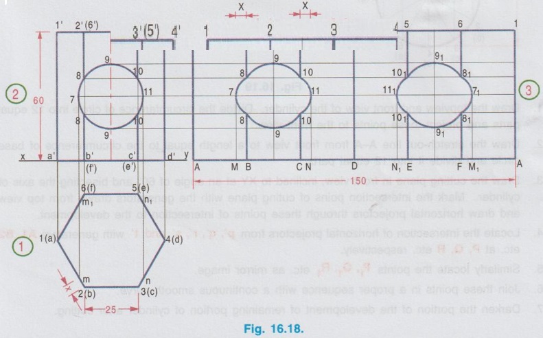
Engineering Graphics: Unit IV (b): Development of Surfaces : Tag: : Construction, Steps, Figure diagram, Example Problems | Engineering Graphics (EG) - Development of Prism
Related Topics
Related Subjects

Engineering Graphics
GE3251 eg 2nd semester | 2021 Regulation | 2nd Semester Common to all Dept 2021 Regulation