Engineering Graphics: Unit IV (b): Development of Surfaces
Development of Objects
Construction, Steps, Figure diagram, Example Problems | Engineering Graphics (EG)
Basically the knowledge of development of solids is required in manufacture of three dimensional objects like tray, pipe-elbow, bucket etc.
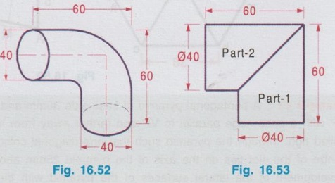
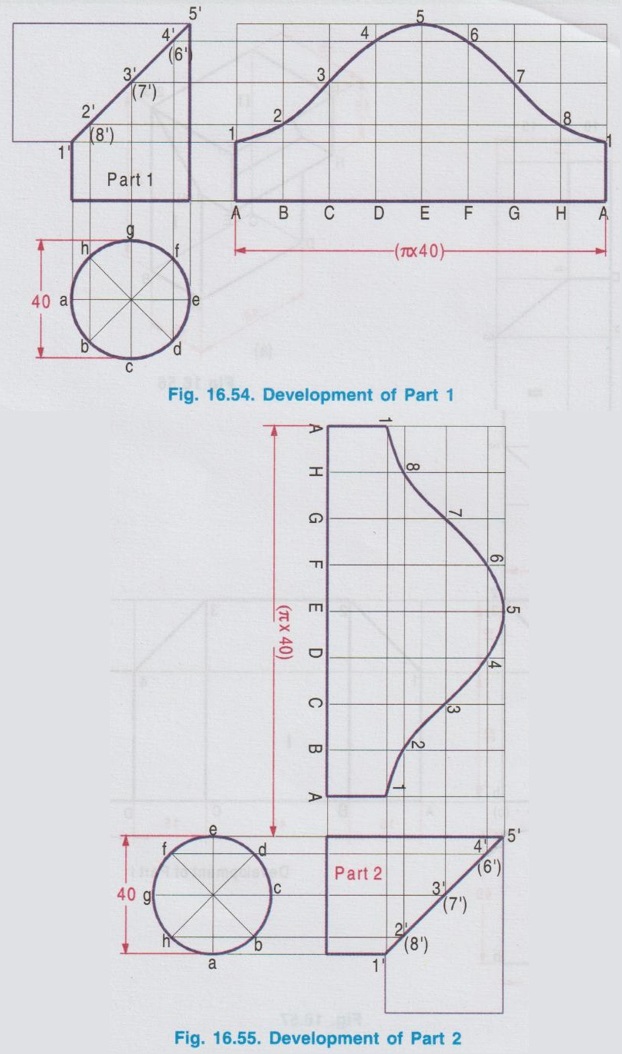
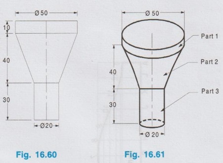
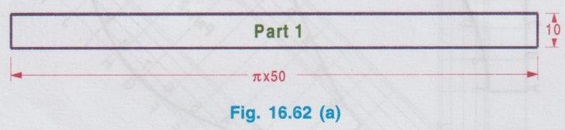
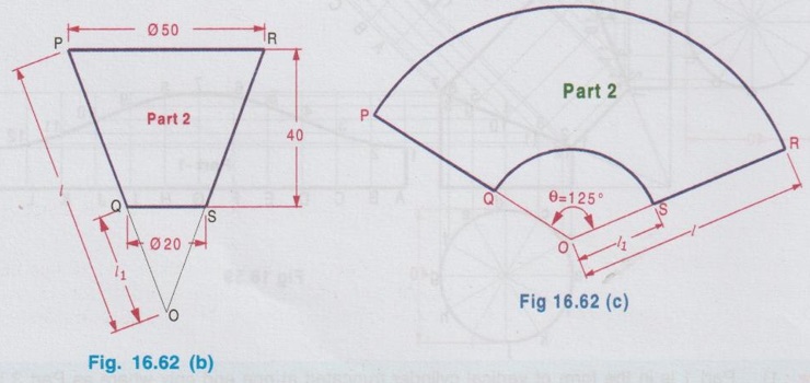
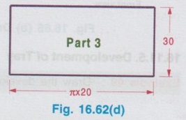
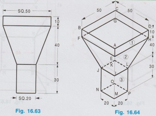
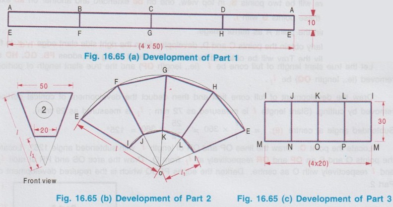
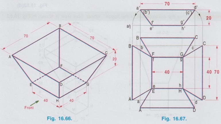
DEVELOPMENT OF OBJECTS Basically the knowledge of development of solids is required in manufacture of three dimensional objects like tray, pipe-elbow, bucket etc. The sheet metal is cut as per the pattern prepared for different portions of the object and then joined by folding or bending to the required shape and the joints are made by welding, riveting, soldering etc., Development of some of the widely used objects are presented in this section. Example 44: Develop the lateral surface of a 90° pipe elbow. Each pipe has a diameter of 40 mm. The maximum length of one leg of the elbow is 60 mm. The pictorial view of 90° pipe elbow is shown in Fig. 16.52, in which two truncated cylinders are joined. Let the parts be part 1 and part 2 as shown in front view (Fig. 16.53). The development of parts 1 and 2 are drawn separately as shown below in Fig. 16.54 and Fig. 16.55. 1. Draw the top view of each part as circle. 2. Divide the circle into eight equal divisions and project them to the front view and mark the points of intersection on the intersection line of the cylindrical portion. 3. Draw the stretch-out line and divide into eight equal parts. 4. Transfer the points to the development and Join them by a smooth curve. Example 45: Draw the development of the hopper shown in Fig. 16.56. Example 46: Draw the development of three piece elbow whose front view is shown in fig.16.58. Note: 1) Part 1 is in the form of vertical cylinder truncated at one end only where as Part 3 is in the form of horizontal cylinder truncated at one end. But Part 2 is in the form of cylinder having its axis inclined and is truncated at both the ends. 2) As Part 1 and Part 3 are identical development of eiher part 1 (or) part 3 only may be drawn Example 47: Draw the development of the funnel, whose front view is shown in Figure 16.60. The pictorial view of funnel is shown in Fig. 16.61. The funnel consists of 3 parts, Part 1 is a hollow cylinder of diameter 50mm and height 10 mm. Part 2 is an inverted frustrum of hollow cone of base diameter 50 mm, height 40 mm and diameter 20 mm at cut- section. Part 3 is a hollow cylinder of diameter 20 mm and height 30 mm. Hence these three parts may be developed separately by the usual method. Development of Part 1 Development of Part 1 is in the shape of a rectangle, length equal to the circumference of base circle of cylinder (ie., π x 50 mm) and height 10 mm. Development of Part 2 The front view of part 2 is shown in figure 16.62(b). Since it is a frustum of a cone, its apex to be located first. Hence extend the slant edges PQ and RS to meet at O. Clearly the top view of slant edge PQ (or RS) is parallel to the reference axis XY. Hence the length of slant edge PQ in front view represents the true slant length. Let the true slant length of full cone be l (ie., length OP) and the true slant length of portion removed (ie., length OQ) be l1. Draw the development of full cone first and then deduct the development of conical portion removed by cutting. (Slant length l is measured as 72 mm; l1 is measured as 29 mm). Locate the point O. Draw the lines OP and OR of length l with subtended angle 125°. Locate the points Q and S on OP and OR respectively at l1 from O. Draw the arcs QS and PR at radii l1 and l respectively with O as centre. Darken the edges PRSQ which is the required development of Part 2. Development of Part 3 Development of Part 3 is in the shape of rectangle, length equal to (π x 20) mm and height 30 mm. Example 48: Draw the development of the hopper, whose front view is shown in Fig. 16.63. The front view is similar to that of the previous problem, but the hopper is square in shape. The pictorial view of the hopper is shown in Fig. 16.64. Part (1) and Part (3) are hollow square prisms. Part (1), has 50 mm base and 10 mm height where as Part (3) has 20 mm base and 30 mm height. Part (2) is an inverted frustum of square pyramid bottom base 50 mm and top base 20 mm, height being 40 mm. These 3 parts are developed separately as shown in Fig. 16.65. Example 49: Draw the development of the tray, whose pictorial view is shown in Fig. 16.66. Construction: 1. Draw the top view as two concentric squares abcd and efgh and project for front view. 2. Extend the base e'h' in front view. 3. With e' as centre and e'a' as radius draw an arc to cut the extension of base at a1'. 4. Project the point a1' to the top view to cut the line bc extended at B. 5. With b as centre and bB as radius draw an arc in top view to cut the line ab extended at B. (There will be two points B, in top view, one on bc extended and another on ab extended) 6. Join these points B with f. 7. Obtain the point A as mirror image. 8. Similarly obtain the points C and D, developing from the right side slant edge h'd' in front view. Finally the Tray will be obtained by folding the sheet along the edges FB, GC, HD and EA.1. Development of Pipe-Elbow
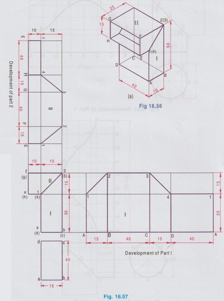
2. Development of Hopper
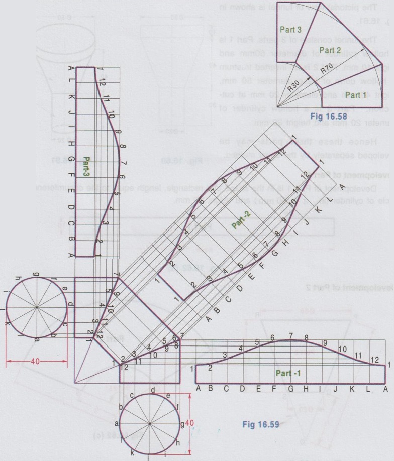
3. Development of three piece elbow
4. Development of Funnel

5. Development of Tray
Engineering Graphics: Unit IV (b): Development of Surfaces : Tag: : Construction, Steps, Figure diagram, Example Problems | Engineering Graphics (EG) - Development of Objects
Related Topics
Related Subjects

Engineering Graphics
GE3251 eg 2nd semester | 2021 Regulation | 2nd Semester Common to all Dept 2021 Regulation