Engineering Graphics: Unit IV (b): Development of Surfaces
Development of Cylinder
Construction, Steps, Figure diagram, Example Problems | Engineering Graphics (EG)
Development of cylinders are also developed by parallel line method in a similar way as the prisms.
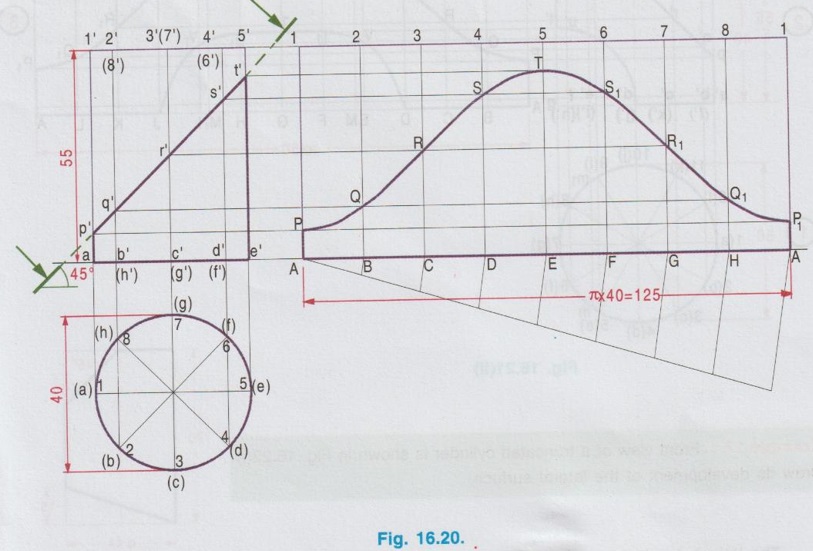
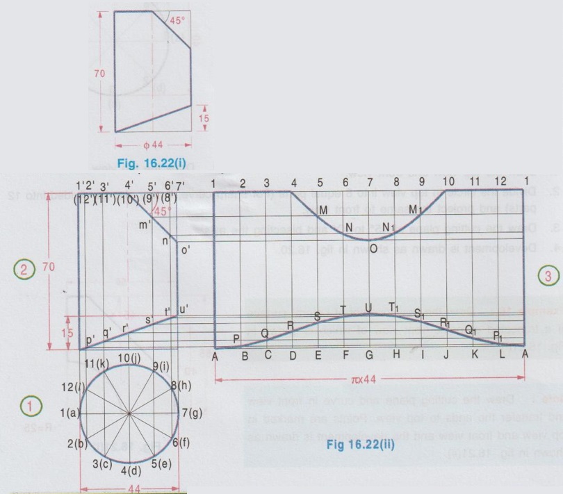
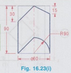
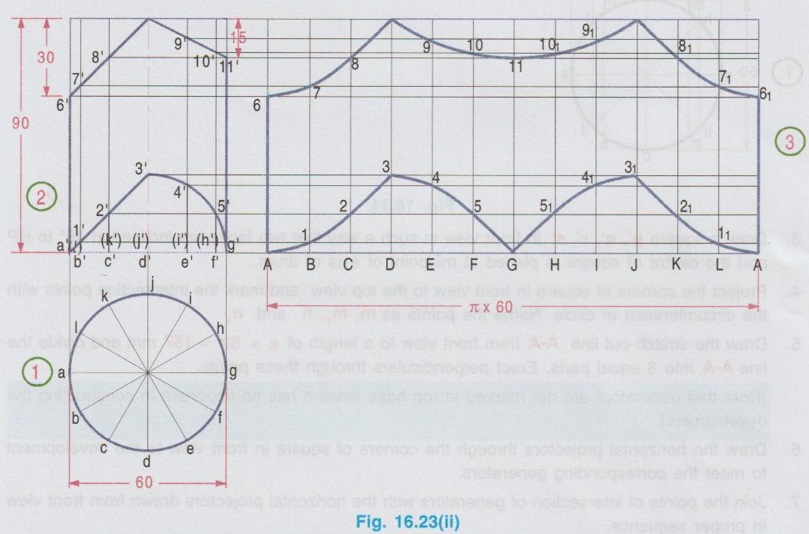
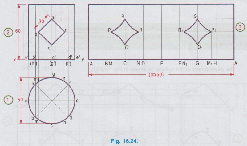
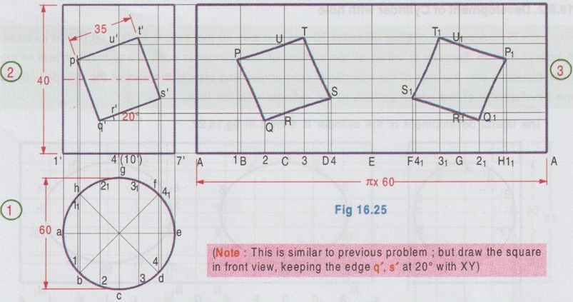
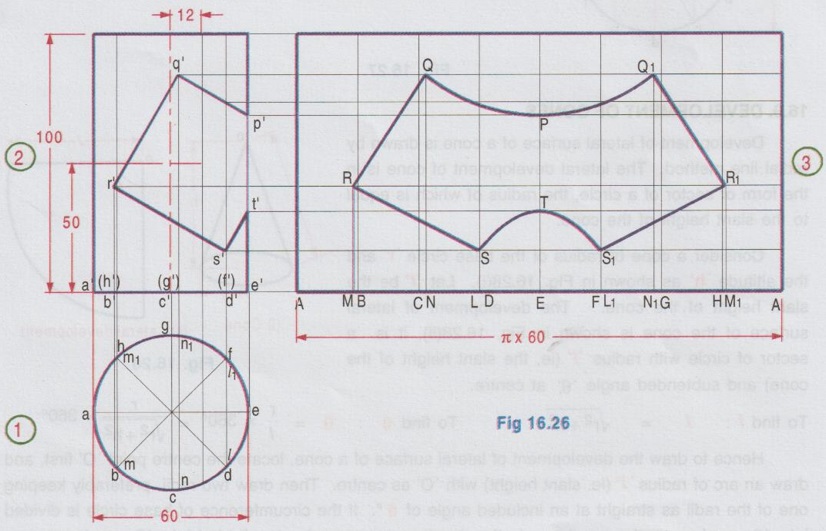
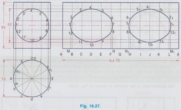
DEVELOPMENT OF CYLINDER Development of cylinders are also developed by parallel line method in a similar way as the prisms. Length of stretch out line in development is equal to the circumference of the base circle of the cyliner. For getting sharp curved edge on development, the circumference of the base circle is normally divided into 12 equal parts. Truncated cylinders, cylinders with cut out (or) hole, perpendicular bas to the axis of cylinder are dealt in this section. Example 14: A cylinder of diameter 50 mm and axis height 60 mm is cut by a plane inclined at 60° to HP and bisecting the axis. Draw the lateral development. 1. Draw the topview and front view of the cylinder. Divide the circumference of circle into 12 equal parts and project these points to the front view. 2. Draw the stretch-out line A-A from front view to a length equal to the circumference of base circle and divide it into 12 equal parts. 3. Draw the cutting plane in front view, inclined to XY at an angle of 60° and bisecting the axis of cylinder. Mark the intersection poins of cuting plane with the generators drawn from top view and draw horizontal projectors through these points of intersection to the development. 4. Locate the intersection of horizontal projectors from p', q', r', s' and t' with generators A1, B2 etc. at P, Q, R etc. respectively. 5. Similarly locate the points P1, Q1, R1 etc. as mirror image. 6. Join these points in a proper sequence with a continuous smooth curve. 7. Darken the portion of the development of remaining portion of cylinder after cutting. Example 15: Draw the development of truncated cylinder base dia 40mm and 55mm long stands on its base on HP. It is cut by a plane inclined at 45° to HP and perpendicular to VP, passing through the mid point of the axis. Draw the development of the lateral surface of the cylinder. 2. Divide the circle in top view into 8 equal parts (For sharp curve, it may also be divided into 12 parts) and project the same to front view. 3. Draw the cutting plane at 45° to XY and bisecting the axis. 4. Development is drawn as shown in fig. 16.20. Example 16: Draw the development of Lateral surface of a truncated cylinder, front view of which is shown in Fig. 16.21(i). Note: Draw the cutting plane and curve in front view and transfer the ends to top view. Points are marked in top view and front view and the development is drawn as shown in fig. 16.21(ii). Example 17: Front view of a truncated cylinder is shown in Fig. 16.22(i). Draw its development of the lateral surface. The lateral development of the cylinder is shown in Fig. 16.22(ii). Example 18: Fig. 16.23(i) shows the front view of a truncated cylinder 90 with 60 mm base diameter and 90 mm long axis. Draw the development of its lateral surface. The development of the cylinder is shown in Fig. 16.23(ii). Note: Generators with the cutting planes are marked as 1′, 2′ etc. in front view, not at the top base of cylinder. Example 19: A square hole of 25 mm side is cut in a cylindrical drum of 50 mm diameter and 60 mm height in such a way that the faces of the hole are inclined at 45° to HP and axis intersects with that of the drum at right angles. Draw the development of its lateral surface. 1. Draw the top view as a circle of diameter 50 mm. Project the topview and complete the front view as a rectangle of base 50 mm and height 60 mm. 2. Divide he circumference of circle in top view into 8 equal parts and project these points to the front view. 3. Draw a square p', q', r', s' in front view in such a way that two faces are inclined at 45° to HP and the centre of square is placed at midpoint of axis of drum. 4. Project the corners of square in front view to the top view and mark the intersection points with the circumference of circle. Name the points as m, m1, n and n1 5. Draw the stretch-out line A-A from front view to a length of π × 50 = 157 mm and divide the line A-A into 8 equal parts. Erect perpendiculars through these points. (Note that generators are not marked at top base since it has no important in constructing the development). 6. Draw the horizontal projectors through the corners of square in front view to the development to meet the corresponding generators. 7. Join the points of intersection of generators with the horizontal projectors drawn from front view in proper sequence. Note that a cutting line in a cylinder will converge to the form of an arc in the development. Hence PQ, QR, RS and SP (also the mirror image P1 Q1, Q1 R1 R1 S1 and S1 P1) in the development are arc of circles. Example 20: A cylinder of 60 mm diameter and axis 70 mm long is standing on its base on HP. A horizontal square cut of 35 mm side is made through the cylinder in such a way that the axis of the cut is parallel to HP and bisects the axis of the cylinder and a side of the cut is inclined at 20° to HP. Develop the lateral surface of the cylinder. The development is shown in Fig. 16.25. Example 21: A cylindrical drum of 60 mm diameter and 100 mm height is resting on its base on HP. A square hole with 50 mm side is cut through the drum such that one of the faces of the square cut is making 30° with HP. The axis of the square cut is perpendicular to VP and 12 mm away from the axis of the cylinder. Draw the development of the cylinder with square cut. The development of the cylinder is shown in Fig. 16.26. Example 22: A cylinder of base diameter 70 mm and axis 80 mm long is resting on HP on its base. A hole of 50 mm diameter is drilled on the surface of the cylinder in such a way that the axis of the hole intersects with the axis of the cylinder at right angles and bisects the axis of the cylinder. Draw the development of the lateral surface of the cylinder with the hole. The lateral development of the cylinder is shown in fig. 16.27.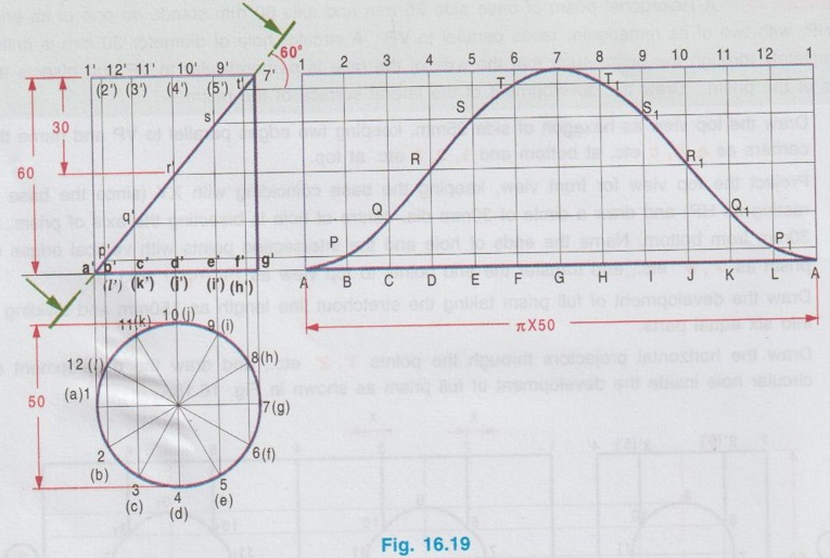
 1. Draw the top view and front view.
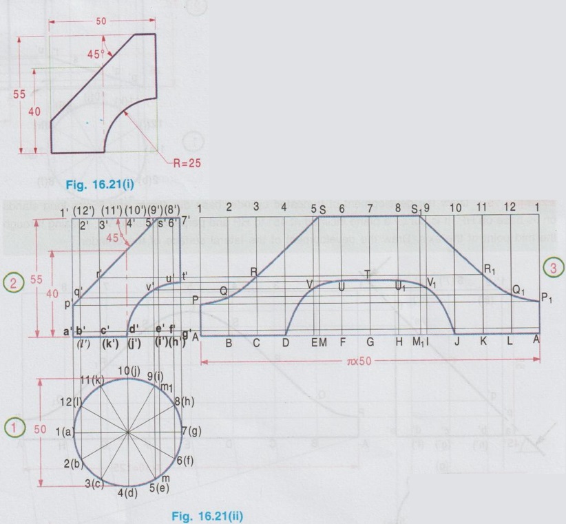
1. Development of Cylinder with cutout
2. Development of Cylinder with hole
Engineering Graphics: Unit IV (b): Development of Surfaces : Tag: : Construction, Steps, Figure diagram, Example Problems | Engineering Graphics (EG) - Development of Cylinder
Related Topics
Related Subjects

Engineering Graphics
GE3251 eg 2nd semester | 2021 Regulation | 2nd Semester Common to all Dept 2021 Regulation