Hydraulics and Pneumatics: Unit IV: Pneumatic and Electro Pneumatic Systems
design of single-actuator pneumatic circuits
control of a single-acting pneumatic cylinder
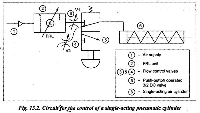
Fig.13.2 illustrates a simple pneumatic circuit of a single-acting air cylinder being controlled by a 3/2 DC valve. This circuit has a FRL unit, a push-button operated spring- return 3/2 DC valve, and a single-acting pneumatic cylinder.
I. DESIGN OF SINGLE-ACTUATOR PNEUMATIC CIRCUITS 1. Circuit Fig.13.2 illustrates a simple pneumatic circuit of a single-acting air cylinder being controlled by a 3/2 DC valve. This circuit has a FRL unit, a push-button operated spring- return 3/2 DC valve, and a single-acting pneumatic cylinder. 2. Operation Extension: When the push-button is pressed, the 3/2 DC valve is shifted to bottom envelope flow path configuration. So the compressed air flows into the blind end of the cylinder and hence the cylinder extends. Retraction: When the push-button is released, the 3/2 DC valve is shifted to top envelope flow path configuration. Now the spring located at the rod end of the cylinder retracts the piston to exhaust the air to the atmosphere. In this circuit, the adjustable flow control valves V1 and V2 are used to control the speed of extension and retraction of the cylinder. It may be noted in the circuit that the short dashed line leading from the exhaust port represents the exhausted air released directly into the atmosphere.CONTROL OF A SINGLE-ACTING PNEUMATIC CYLINDER
Hydraulics and Pneumatics: Unit IV: Pneumatic and Electro Pneumatic Systems : Tag: : control of a single-acting pneumatic cylinder - design of single-actuator pneumatic circuits
Related Topics
Related Subjects

Hydraulics and Pneumatics
ME3492 4th semester Mechanical Dept | 2021 Regulation | 4th Semester Mechanical Dept 2021 Regulation