Basic Electrical and Electronics Engineering: Unit V: Measurements and Instrumentation
Data Acquisition Systems
Block Diagram, Working Principle, Problems with solutions
A typical data acquisition system consists of individual sensors with the necessary signal conditioning, data conversion, data processing, multiplexing, data handling and associated transmission, storage and display systems.
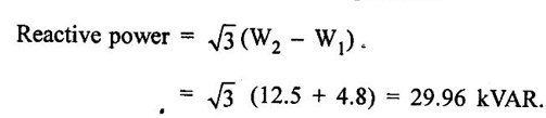
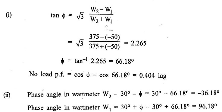
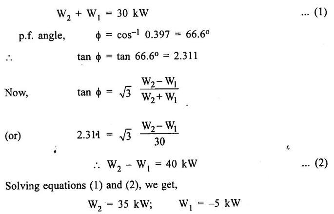
DATA ACQUISITION SYSTEMS A typical data acquisition system consists of individual sensors with the necessary signal conditioning, data conversion, data processing, multiplexing, data handling and associated transmission, storage and display systems. Data may be transmitted over long distances or short distances. The data may be displayed on a digital panel or on a CRT. The same may be stored temporarily (for immediate use) or permanently for future reference. Data acquisition normally relates to the process of collecting the input data in digital form as rapidly, accurately and economically as required. The basic instrumentation used may be a digital panel meter (DPM) with digital outputs, a shift digitizer or a modern high speed resolution device. To match the input requirement of the converter with the output available from the sensor, some sort or scaling and off-selting is necessary and is performed with an amplifier/attenuator. For converting analog information from more than one source, either additional converters or a multiplexer may be required; to increase the speed with which information is to be accurately converted, a sample and hold circuit may be required. A setematic block diagram of a general Data Acquisition System (DAS) is given in fig.5.23 Data acquisition systems are used in a large and even increasing number of applications in a variety of industrial and scientific areas, such as power systems, biomedical, aerospace and telemetry industries. The types of DAS, whether analog or digital, depends mainly only the intended use of the recorded input data. Normally, analog data systems are used when wide bandwidth is required and high accuracy is not required. Digital systems are employed when the physical process being monitored is slowly varying (narrow bandwidth) and high accuracy and low per channel cost in desired. The advent of real-time computation and control by means of digital computers is primarily responsible for the development of telemetry systems. Telemetry (telemetering) is useful in presentation of measured values at a location remote from the site of measurement. The subject of telemetry plays vital role in the centralized and supervision of power generation and distribution systems. The important factors that decide the configuration and subsystems of the DAS are given below: (i) Accuracy and resolution (ii) Number of channels to be monitored (iii) Analog or digital signal (iv) Single/multichannel (v) Sampling rate per channel (vi) Signal conditioning requirements of each channel (vii) Cost DAS must be able to collect, summarise and store data for diagnosis of operation and record purpose. It must be able to compute unit performance indices using on-line, real-time data. Problem 5.1 Two-wattmeter method is used to measure the power absorbed by a 3-phase induction motor. The wattmeter readings are 12.5kW and -4.8 kW. Find (i) the power absorbed by the machine, (ii) load power factor and (iii) reactive power taken by the load. Solution : W2 = 12.5 kW; W1 = -4.8 kW Note that W2 is the higher-reading wattmeter. Further W2 – W1 is the algebraic difference of two wattmeter readings. Since the load p.f is less than 0.5, the lower-reading wattmeter must read downscale as is evident from the data of the problem. Problem 5.2 Two-wattmeter method is used to measure the power taken by a 3-phase induction motor on no load. The wattmeter readings are 375W and −50W. Calculate (i) Power factor of dc motor at no load (ii) phase difference of voltage and current in two wattmeters. Solution : Problem 5.3 A 3-phase motor load has a p.f of 0.397 lagging. Two wattmeters connected to measure power show the input as 30kW. Find the reading on each wattmeter. Solution : Since the load p.f is less than 0.5, the lower-reading wattmeter W1 gives downscale reading. The upscale reading of this wattmeter can be obtained by reversing the connections of its current or potential coil.

Basic Electrical and Electronics Engineering: Unit V: Measurements and Instrumentation : Tag: : Block Diagram, Working Principle, Problems with solutions - Data Acquisition Systems
Related Topics
Related Subjects

Basic Electrical and Electronics Engineering
BE3251 2nd semester Mechanical Dept | 2021 Regulation | 2nd Semester Mechanical Dept 2021 Regulation

Basic Electrical and Electronics Engineering
BE3251 2nd Semester CSE Dept 2021 | Regulation | 2nd Semester CSE Dept 2021 Regulation