Theory of Machines: Unit I: Kinematics of Mechanisms
coriolis component of acceleration
Kinematics of Mechanisms - Theory of Machines
We have seen that the total acceleration of a point with respect to another point on a rigid link is the vector sum of its radial and tangential acceleration components
CORIOLIS COMPONENT OF ACCELERATION
1. What is it?
• We
have seen that the total acceleration of a point with respect to another point
on a rigid link is the vector sum of its radial and tangential acceleration
components i.e., aAB = arBA +
atAB. This is true only when the distance between
the two points is fixed.
• On
the contrary, when the distance between the two points is not fixed (i.e., the
distance varies), then the total acceleration will have one more additional component
known as Coriolis component of acceleration. It is represented by acAB.
In such cases, the total acceleration of that link is the vector sum of its
radial, tangential and Coriolis acceleration components i.e., aAB =
arAB + atAB + acAB.
• The
Coriolis component of acceleration happens only when a point known as
coincident point, on one link is sliding along another rotating link.
In other words, whenever a coincident point exists in a mechanism, we have to
consider Coriolis component of acceleration.
• Examples:
The mechanisms such as crank and slotted lever mechanism, Whitworth quick
return mechanism, oscillating cylinder mechanism and swivelling joint mechanism
require the calculation of Coriolis component of acceleration.
2. Magnitude of Coriolis Component of Acceleration
Consider
a link OA which has a slider B which is free to slide, as shown in Fig.2.23.
With O as centre, let the link OA move, with a uniform angular velocity w, to
its new position OA' such that it is displaced dθ in time dt. The
slider B moves outwards with sliding velocity vs on link OA
and occupies the position B' in the same interval of time.
The
point C is the coincident point with slider on link OA.
The
motion of slider can be explained in the following three stages:
(i)
Motion from C to C' due to rotation of link OA. It is caused by tangential
component of acceleration a'.
(ii)
Motion from C' to B1 due to outward motion along the link OA. It is
caused by radial component ar (or sliding component, as) of
acceleration.
(iii)
Motion from B1 to B' is caused by Coriolis component of acceleration
ac.
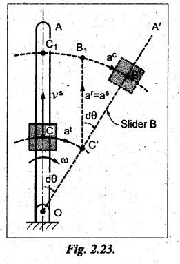
From
the geometry of Fig.2.23,
For
small value of dθ,
Arc
B1B' = B1B'
From
equations (ii) and (iii), we get
where
vs
= Velocity of sliding, and
ω
= Angular velocity of link OA.
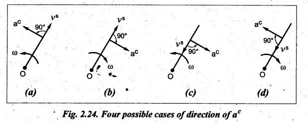
3. Direction of Coriolis Component of Acceleration
• The
direction of Coriolis component of acceleration a is to rotate the sliding
velocity vector vs in the same sense as the angular velocity of OA.
• The
direction of Coriolis component of acceleration is obtained by rotating the
velocity of sliding vector v3 through 90° in the direction of rotation of
angular velocity, ω.
• Since
the direction of ac depends on the direction of vs
and ω, therefore there are four possible cases of direction of ac,
as shown in Fig.2.24.
• It
may be noted that in equation (2.15), the outward direction of velocity of
sliding vs is assumed as positive and the counter clockwise
direction of ω is assumed as positive.
Example 2.11
The driving crank AB of the quick-return mechanism, as shown in
Fig.2.25, revolves at a uniform speed of 200 rpm. Find the velocity and
acceleration of the tool-box R, in the position shown, when the crank makes an
angle of 60° with the vertical line of centres PA. What is the acceleration of
sliding of the block at B along the slotted lever PQ?
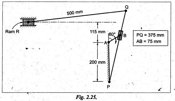
Given data:
NBA
= 200 rpm
Solution: Relative velocity
method.
Procedure:
Step 1: Configuration
diagram: First of all, draw the configuration
diagram, to some suitable scale (say, 1 cm 50 mm), as shown in Fig.2.26(a).
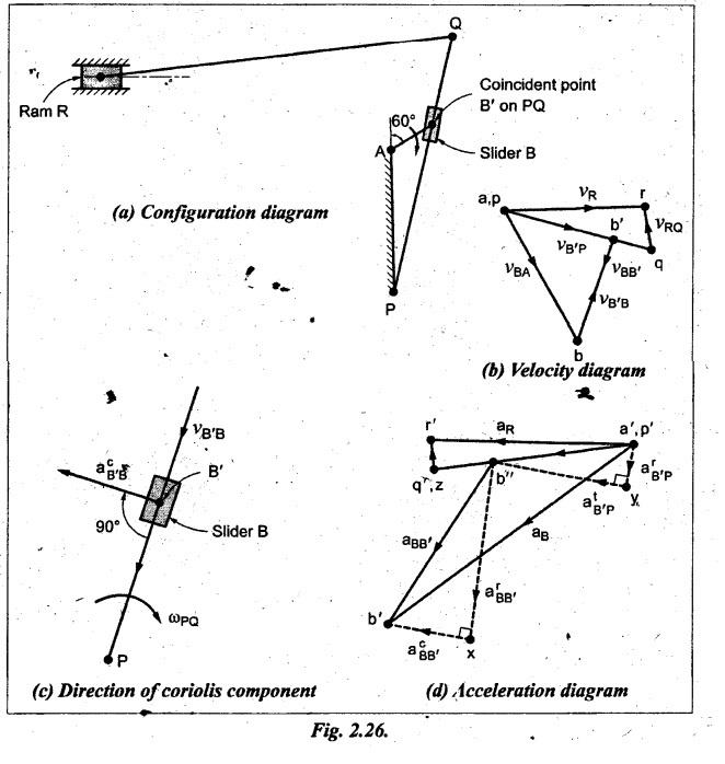
Step 2: Velocity of
input link:
Step 3: Velocity
diagram: Now draw the velocity diagram, to
some suitable scale (say, 1 cm = 0.75 m/s), as shown in Fig.2.26(b).
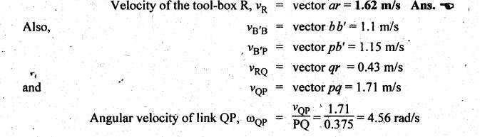
Step 4: Velocity of
various links:
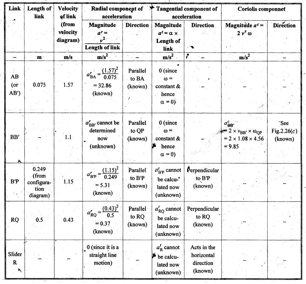
By
measurement from the velocity diagram, we get
Step 5: Acceleration
diagram: The values of radial, tangential and
Coriolis components of acceleration of various links are calculated as shown in
Table 2.9.
Now
using the known values of magnitude and direction of acceleration components,
the acceleration diagram can be constructed, to some suitable scale (say, 1 cm
= 5.5 m/s2), as shown in Fig.2.26(d).
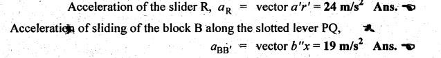
Step 6: Acceleration
of various links:
By
measurement from the acceleration diagram, we get
Theory of Machines: Unit I: Kinematics of Mechanisms : Tag: : Kinematics of Mechanisms - Theory of Machines - coriolis component of acceleration
Related Topics
Related Subjects

Theory of Machines
ME3491 4th semester Mechanical Dept | 2021 Regulation | 4th Semester Mechanical Dept 2021 Regulation