Manufacturing Technology: Unit II: Turning Machines
constructional features of a centre lathe
Turning Machines - Manufacturing Technology
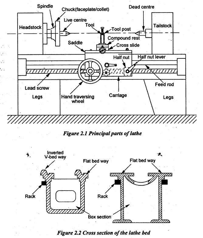
The principal parts of an engine lathe are labelled and shown in Figure 2.1. The following are the principal parts of the lathe.
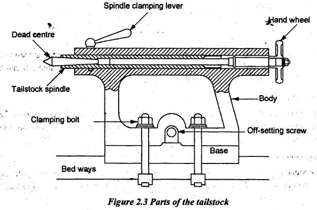
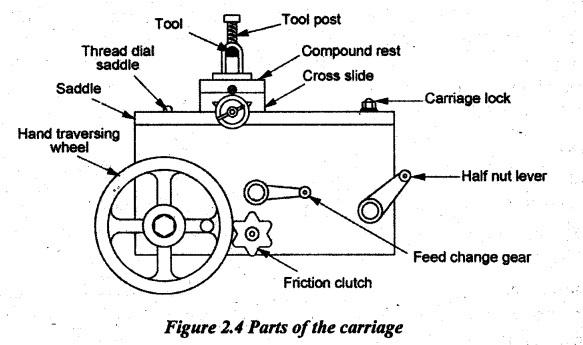
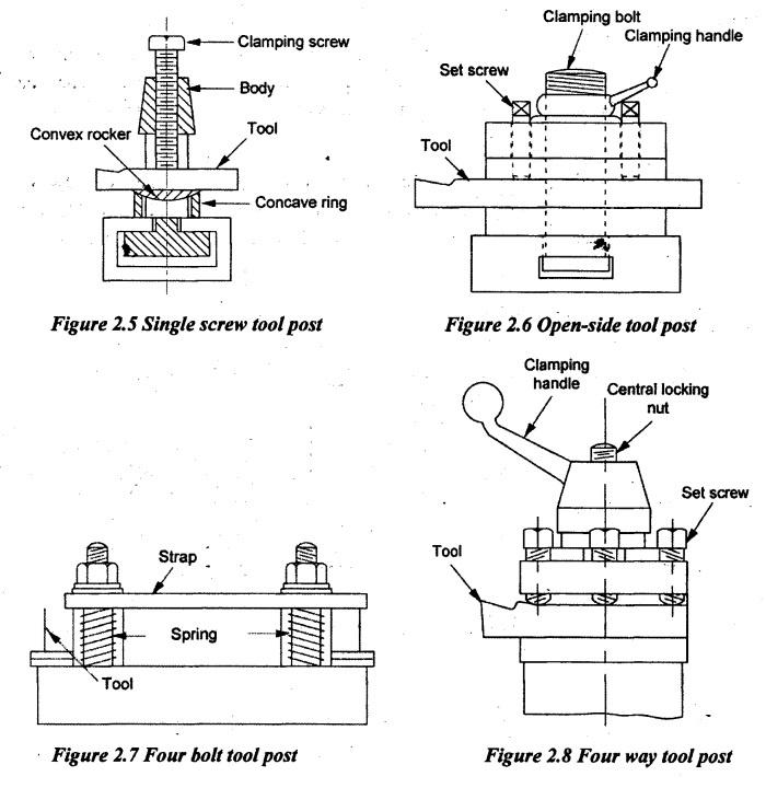
CONSTRUCTIONAL FEATURES OF A CENTRE LATHE The principal parts of an engine lathe are labelled and shown in Figure 2.1. The following are the principal parts of the lathe. (i) Bed (ii) Headstock (iii) Tailstock (iv) Carriage (v) Feed mechanism. A brief description of these parts is as follows: Bed is the base of machines. It carries a headstock on its left end and tailstock on its right end. The carriage is mounted at the middle of bed. The headstock is a stationary one. Both tailstock and carriage move over the bed. The bed has V and dovetail guideways as shown in Figure 2.2. The bed is very strong to resist the cutting forces and vibrations. It is rigidly held by cross ribs supported by cast iron supports. I guideways are very accurately machined for getting the accurate dimensions in jobs. It should sufficiently be rigid to prevent the deflection under high cutting pressure transmitted through the tool post and carriage. There is a rack under the front way of the bed. A pinion gear is meshed with rack for moving the carriage when the hand wheel is turned. The bed is made of cast iron alloyed with nickel and chromium. The headstock assembly is permanently fastened to the left end of the bed. It carries a hollow spindle so that bars can be passed through it when it is required. The nose of the spindle is threaded to hold the chuck or faceplate. The spindle is rotated by a combination of gears and cone pulleys or by gears alone. The spindle has a taper at the front end for holding centres and other tools have a tapered shank. A live centre can be attached to the spindle. This centre is called live centre because it turns with the work. In taper turning operations, there is no power feed to the compound rest. It is only operated by hand to feed the tool longitudinally or at an angle to the lathe axis. There is a micrometer dial for showing the depth of cut. The headstock has the driving and speed changing mechanisms. The headstock may be of a back-geared type or all geared type. There are speed changing and feed changing levers attached to the headstock. Tailstock is situated at the right end of the bed. It is used for supporting the right end of work. It consists of a taper hole adjusting screw and hand wheel. It can be moved along the bed and clamped to the bed at the desired location. Tailstock is also used to hold a drill, reamer or tap for drilling, reaming or tapping operations. Tailstock consists of two main parts. The lower part directly rests on bed ways and the upper part rests on the lower part (base). Adjusting screws hold the two parts together. The upper body of the tailstock can be moved towards or away from the operator for taper turning operations. The tailstock body is bored and the tailstock spindle or quill moves through it. The spindle can axially be moved by means of a hand wheel. A dead centre is fixed into the taper hole of the spindle for supporting the right end of the work. The carriage is a moving part that slides over the guideways between headstock_and tailstock. It carries the following parts as shown in Figure 2.4. (i) Saddle (ii) Cross slide (iii) Compound rest (iv) Tool post (v) Apron. (i) Saddle: It is an H-shaped component fitted across the lathe bed. It moves along the guideway. It carries the cross slide and tool post to provide various kinds of motion to tools. It can be moved anywhere along the bed and locked to the required position. (ii) Cross slide: The cross slide is attached to the saddle. It carries the compound rest and tool post. The cross slide can be moved by power or by hand. There is a micrometer dial fitted on the cross slide handwheel with an accuracy of 0.05mm. (iii) Compound rest: Compound rest is mounted on the top of the cross slide. It is used for supporting the tool post and cutting tool in various positions. The base of the compound rest is marked in degrees. The tool post can be swivelled to various angular positions for different turning operations. (iv) Tool post: A tool post is used to hold various tools and tool holders to create convenient working conditions. The tool post is fitted over the compound rest. The various types of tool posts are as follows. (a) Single screw tool post (b) Open side tool post (c) Four bolt tool post (d) Four way tool post. (a) Single screw tool post: This tool post is only used to hold a single tool. The tool is clamped by a clamping screw. The tool rests on the top flat surface of the convex rocker. The convex rocker has a convex surface at its bottom. This convex rocker is placed over a concave ring. The height of the tool is adjusted by this arrangement. (b) Open-side tool post: This type of tool post is shown in Figure 2.6. The tool is held in position by the set screws. In order to adjust the height of the cutting point, the parallel packing strips are used. The tool post is fitted on the compound rest by using a clamping bolt through T-slot. The tool post can be tilted to any angle by loosening the clamping bolt and clamped. (c) Four bolt tool post: In this type of a tool post, two tools may be held in position by two straps and four bolts. The tool height is adjusted by placing parallel strips under the tool. It is generally used in heavy lathes as it gives more support to the tool. (d) Four-way tool post: It is a commonly used tool post nowadays because it facilitates to hold four various tools in a tool post at a time as shown in Figure 2.8. It can be swivelled in the central screw and clamped at any angle. Here, the tool height can be adjusted by using parallel strips. (v) Apron: The apron is fitted to the saddle and hung at the front side of bed. It has several gears, levers and clutches for moving the carriage with the lead screw for thread cutting. It has a split nut for automatic thread cutting operation. The detailed mechanism is explained in further sections.1. Bed:
2. Headstock:
3. Tailstock:
4. Carriage:
Manufacturing Technology: Unit II: Turning Machines : Tag: : Turning Machines - Manufacturing Technology - constructional features of a centre lathe
Related Topics
Related Subjects

Manufacturing Technology
ME3493 4th semester Mechanical Dept | 2021 Regulation | 4th Semester Mechanical Dept 2021 Regulation