Manufacturing Technology: Unit IV: CNC Machines
computer numerical control (cnc) machine tools
CNC Machines - Manufacturing Technology
Rapid development in the field of electronics such as integrated circuit, large scale integrated circuits and development of minicomputer lead to the development of minicomputers-based CNC machine tools.
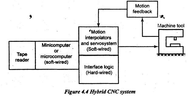
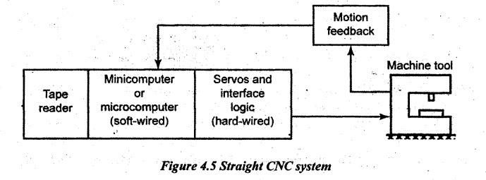
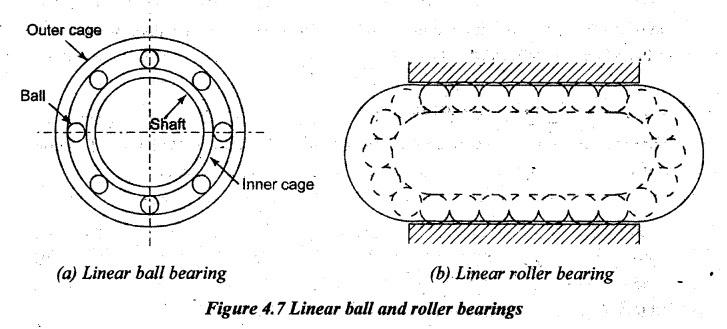
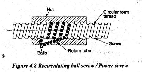
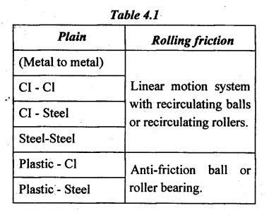
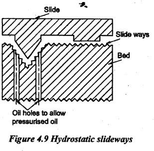
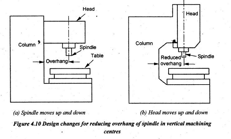
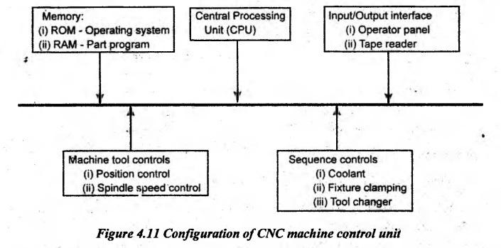
COMPUTER NUMERICAL CONTROL (CNC) MACHINE TOOLS Rapid development in the field of electronics such as integrated circuit, large scale integrated circuits and development of minicomputer lead to the development of minicomputers-based CNC machine tools. Computer Numerical Control (CNC) is a NC system that utilizes a stored program to perform the basic numerical control functions. A mini or microcomputer-based controller unit is used. CNC is a microprocessor-based control system which accepts a set of program instructions, processes and feeds the output control information to a machine tool, accepts the feedback information from the machine tool and it assures the proper motion, speed to perform the operations. Otherwise, CNC machines are programmed and controlled by a computer so it can offer very short set-up time and the flexibility is more to run batches from one-offs to several thousand. The development of CNC machines is an outstanding contribution to the manufacturing industries. It has made possibility for the automation of the machining process with flexibility to handle a small to medium batch of quantities in part production. The external appearance of CNC is very similar to NC. The part programs are entered in a similar manner. The punched tape readers are common devices for both CNC and NC systems. In CNC, the program is entered once and then it is stored in the computer memory whereas in conventional NC machines, the punched tape is cycled through the tape reader for every workpiece. The machine follows a predetermined sequence of machining operations at the predetermined speeds necessary to produce a workpiece of the right shape and size and thus according to completely predictable results. A different product can be produced through reprogramming and a low- quantity production run of different products is justified. When compared to NC, CNC offers more flexibility and computational capability. The reprogramming is easy because of this facility. CNC is often termed as softwired NC. Computer NC systems include additional features beyond what is feasible with conventional hard-wired NC. These features, many of which are standard on most CNC MCUs whereas others are optional, include the following: 1. Storage of more than one part program: With improvements in computer storage technology, newer CNC, controllers have the sufficient capacity to store multiple programs. Controller manufacturers generally offer one or more memory expansions as options to the MCU. 2. Various forms of program input: Whereas the conventional (hard-wired) MCUs are limited to a punched tape as the input medium for entering part programs, CNC controllers generally possess the multiple data entry capabilities, such as such as floppy disk, hard disk, CD ROM, DVD, USB flash drive, or RAM card, RS-232 communications with external computers and manual data input. 3. Program editing at the machine tool: CNC permits a part program to be edited while it resides in the MCU computer memory. Hence, the process of testing and correcting a program can be done entirely at the machine site rather than returning to the programming office to correct the tape. After correcting and optimizing the program, the revised version can be stored on a punched tape or other media for future use. 4. Fixed cycles and programming subroutines: The increased memory capacity and the ability to program the control computer provide the opportunity to store frequently used machining cycles as macros that can be called by the part program. Instead of writing the full instructions for the particular cycle into every program, a call statement is included in the part program to indicate that the macro cycle should be executed. 5. Interpolation: Some of the interpolation schemes are normally executed only on a CNC system because of the computational requirements. Linear and circular interpolations are sometimes hard-wired into the control unit, but helical, parabolic and cubic interpolations are usually executed in a stored program algorithm. 6. Positioning features for setup: Setting up the machine tool for a given workpiece involves installing and aligning a fixture on the machine tool table. It must be accomplished so that the machine axes are established with respect to the workpiece. The alignment task can be facilitated using certain features made possible by software options in a CNC system. Position set is one of these features. With the position set, the operator is not required to locate the fixture on the machine table with extreme accuracy. Instead, the machine tool axes are referenced to the location of the fixture by using a target point or set of target points on the work or fixture. 7. Tool length compensation: The setting of the depth of the tool to an exact is very difficult and time-consuming. Therefore, it may be convenient to set the tool to an approximate dimension and then it adjusts the difference by some external means switches on control systems. This procedure is called tool length compensation. It allows the programmer to ignore the precise length of each tool as a program is written. CNC system facilitates this feature. 8. Acceleration and deceleration calculations: This feature is applicable when the cutter moves at high feed rates. It is designed to avoid tool marks on the work surface that would be generated due to machine tool dynamics when the cutter path changes abruptly. Instead, the feed rate is smoothly decelerated in anticipation. of a tool path change and then it is accelerated back up to the programmed feed rate after the direction change. 9. Communications interface: With the trend toward-interfacing and networking in plants today, the most modem CNC controllers are equipped with a standard RS-232 or other communications interface to allow the machine to be linked to other computers and computer-driven devices. It is useful for various applications, such as: (1) downloading part programs from a central data file as in distributed NC; (2) collecting operational data, such as workpiece counts, cycle times, and machine utilization; and (3) interfacing with peripheral equipment, such as robots that load and unload parts. 10. Diagnostics: Many modern CNC systems possess an on-line diagnostics capability that monitors certain aspects of the machine tool to detect malfunctions or signs of impending malfunctions or to diagnose system breakdowns. The CNC systems are broadly classified as follows: (a) According to the structure of the control system used 1. Analog system 2. Digital system. (b) According to the type of control loop used 1. Closed-loop system 2. Open-loop system. (c) According to the type of tool motion control system used 1. Point-to-point or positioning system 2. Continuous path system. a) Straight-cut system b) Contouring system (d) According to the programming mode used 1. Absolute mode 2. Incremental mode. (e) According to the controller design 1. Hybrid CNC 2. Straight CNC. The principal functions of CNC systems in machine tools are as follows: 1. Machine tool control 2. In-process compensation 3. Diagnostics. 1. Machine tool control: It is the important function of the CNC system. It includes the conversion of the part program instructions into machine tool movements. It is done through the computer interface and servosystems. Some of the control funetions, such as circular interpolation can be more efficiently accomplished with hardwired circuits and with the computer. This feature has led to the development of two alternative controller designs in CNC. They are as follows: (a) Hybrid CNC (b) Straight CNC. (a) Hybrid CNC: In Hybrid CNC systems, the controller consists of two major parts such as soft-wired computer and hardwired logic circuits as shown in Figure 4.4. The hardwired logic circuits perform the functions such as machine tool feed rate generation and circular interpolation. The soft-wired computer performs the remaining control functions. The use of hardwired logic circuits saves the computer from performing the calculations and hence, a less expensive component is required in the hybrid CNC systems. (b) Straight CNC: In straight CNC system, the computer software is used to perform all NC functions such as interpolation, feed rate generation, tool position feedback, etc. The hardwired component is used to just interface the computer with the machine tool and the operator console. Figure 4.5 shows the straight CNC system. Since all the functions are carried out by the computer, it should be more powerful. The major advantage of this system is its flexibility.'It is possible to make changes in the interpolation programs which are not possible in hybrid systems. 2. In-process compensation: This function involves the real time correction of the machine tool movements for changes errors which occur during process. Some of the in-process compensation features include the following: (a) Correction of errors sensed by the in-process inspection probes and gauges (b) Recomputation of axis position by locating datum reference on a workpiece (c) Accurate calculation of the tool life (d) Offset adjustment for cutter radius compensation and tool length compensation (e) Selection of alternative tooling as per instructions (f) Adaptive control adjustments to speed and/or feed. 3. Diagnostics: Modern CNC machines are equipped with diagnostics capacity. It assists in maintaining and repairing the system. The diagnostics system would be able to identify the reason for a downtime so that it could be minimised by attending it quickly. Another function of diagnostic system is that it gives warning about the forthcoming failure of a certain component. The diagnostic system disconnects the faulty component automatically when one of the machine components fails and activates the redundant component. The different elements of the CNC systems are as follows: (a) Part program (b) Program input device (c) Machine control unit (d) Machine tool (e) Driving system (f) Feedback devices (g) Display unit Figure 4.6 shows the block diagram of arrangement of these elements. (a) Part program: Part programming contains geometric data about the part and motion information to move the cutting tool with respect to the workpiece. Basically, the machine receives instructions as a sequence of blocks containing commands to set machine parameters; speed, feed and other relevant information. A block is equivalent to a line of codes in a part program. (b) Program input device: Figure 4.6 Elements of CNC systems CNC systems generally possess multiple data entry capabilities, such as such as floppy disk, hard disk, CD ROM, DVD, USB flash drive, or RAM card, serial communication ports, and manual data input. In recent years, all computers support USB flash drives to read and write data that make it become more and more popular in CNC machine control unit. The' data transfer between computer and CNC machine tool is often accomplished through a serial communication port. International standards for serial communications are established so that the information can be exchanged in an orderly way. Part programs can be downloaded into the memory of a machine tool or uploaded to the computer for temporary storage by running a communication program on the computer and setting up the machine control to interact with the communication software. (c) Machine control unit: The machine control unit is the heart of the CNC system. The information stored in the computer can automatically be read and converted into electrical signals. The electrical signals operate the servo systems of machine tool. There are two sub-units in the machine control unit: the Data Processing Unit (DPU) and the Control Loop Unit (CLU). (i) Data Processing Unit (DPU): On receiving a part program, the DPU firstly interprets and encodes the part program into internal machine codes. The interpolator of the DPU then calculates the intermediate positions of the motion in terms of BLU (basic length unit) which is the smallest unit length that can be handled by the controller. The calculated data are passed to CLU for further action. (ii) Control Loop Unit (CLU): The data from the DPU are converted into electrical signals in the CLU to control the driving system to perform the required motions. Other functions such as machine spindle ON/OFF, coolant ON/OFF, tool clamp ON/OFF are also controlled by this unit according to the internal machine codes. (d) Machine tool: It can be any type of machine tool or equipment. In order to obtain high accuracy and repeatability, the design and make of the machine slide and the driving lead screw of a CNC machine are of vital importance. The slides are usually machined to high accuracy and coated with the anti-friction material such as PTFE and Turcite in order to reduce the stick and slip phenomenon. Large diameter recirculating ball screws are employed to eliminate the backlash and lost motion. Electrically controlled servo systems allow the slides of a machine tool simultaneously to be driven at the appropriate feeds and direction to machine complex shapes. Other design features such as rigid and heavy machine structure; short machine table overhang, quick change tooling system, etc. also contribute to the high accuracy and high repeatability of CNC machines. (e) Driving system: The driving system is an important component of a CNC machine as the accuracy and repeatability mainly depend on the characteristics and performance of the driving system. The requirement is the driving system which has to response accurately according to the programmed instructions. This system usually uses electric motors although hydraulic motors are sometimes used for large machine tools. The motor is coupled either directly or through a gearbox to the machine lead screw to move the machine slide or the spindle. Three types of electrical motors such as DC servo motor, AC servo motor, and stepping motor are commonly used.' (f) Feedback devices: In order to have a CNC machine operating accurately, the positional values and speed of the axes need to be constantly updated. Two types of feedback devices are normally used: positional feedback device and velocity feedback device. (i) Positional feedback devices: There are two types of positional feedback devices used in CNC machines. They are linear transducer and rotary encoder. The linear transducer is used for direct positional measurement and the rotary encoder is used for angular or indirect linear measurement. A linear transducer is a device mounted on the machine table to measure the actual displacement of the slide in such a way that backlash of screws; motors, etc. would not cause any error in the feedback data. A rotary encoder is a device mounted at the end of the motor shaft or screw to measure the angular displacement. (ii) Velocity feedback device: The actual speed of the motor can be measured in terms of the voltage generated from a tachometer mounted at the end of the motor shaft. DC tachometer is essentially a small generator that produces an output voltage proportional to the speed. The voltage generated is compared with the command voltage corresponding to the desired speed. The difference of the voltages can be then used to actuate the motor to eliminate the error. (g) Display unit: The display unit serves as an interactive device between the machine and operator. When the machine is running, the display unit displays the present status such as the position of the machine slide, the spindle RPM, the feed rate, the part programmes, etc. In an advanced CNC machine, the display unit can show the graphics simulation of the tool path so that part programmes can be verified before the actual machining. Much other important information about the CNC system can also be displayed for maintenance and installation work such as machine parameters, a logic diagram of the programmer controller, error messages and diagnostic data. Some of the important parts of CNC machines tool are as follows: (a) Machine structure, (b) Slideways or guideways, (c) Spindle / spindle bearings 1) Hydrodynamic 2) Hydrostatic 3) Antifriction (d) Spindle drives 1) Electrical drives 2) Hydraulic drives 3) Pneumatic drives (e) Feed drives 1) Servo motor 2) Mechanical transmission system (f) Measuring systems 1) Direct 2) Indirect (g) Controls, software and user interface (h) Gauging (i) Tool monitoring systems 1) Direct 2) Indirect. Some of the important features are described here. (a) Machine structure: The machine structure is the load carrying and supporting member of the machine tool. All motors, drive mechanisms and other functional assemblies of machine tools are aligned to each other and rigidity fixed to the machine structure. The machine structure is subjected to static and dynamic forces and it is, therefore, essential that the structure does not deform or vibrate beyond the permissible limit under the action of these forces. All components of the machine must remain in correct relative positions to maintain the geometric accuracy, irrespective of the magnitude and direction of these forces. The machine structure configuration is also influenced by the consideration of manufacture, assembly and operation. The basic design factors involved in the design of machine structure are as follows. 1. Static load 2. Dynamic load 3. Thermal load (b) Slideways or Guideways: Generally, machine tools are provided with tables, slides, carriages, etc. to carry the workpieces or cutting tools. These parts are mounted in the ways and slide along the ways. They are also fixed on the parts of the machine tools such as a column, housing, bed or knee. Various slideways used in CNC machine tools are elaborately discussed in the further chapter with the required properties of good slideway system. (c) Spindle: The spindle of a machine tool is driven by the power obtained from the drive unit and transmits the same power to the work or tool. In lathe machines, this power is used to hold the workpiece. The main functions of spindles are given below. (i) Centering the job or tool (ii) Holding the job or tool (iii) Rotating the job or tool. So, the spindle should be stiff, stable and short in length. For good stability of the spindle, it should pass minimum distortional strain and it should be close to the front bearing as much as possible. The required properties of good spindles, various spindles used in CNC machine tools with its advantages and limitations are elaborately discussed in coming chapters. (d) Spindle bearings: In CNC machine tools, spindles are mounted on the antifriction bearings. Various types of bearings used to mount spindle are as follows. (i) Preloaded taper roller bearings (ii) Preloaded ball bearings (iii) Hydrostatic journal bearings (iv) Oil retaining bearings. (e) Drive systems: The driving system is a main component of a CNC machine as the accuracy and repeatability mainly depend on the characteristics and performance of the driving system. For obtaining good accuracy and better performance, the driving system has to response accurately according to the programmed instructions. This system usually uses electric motors although ́hydraulic motors are sometimes used for large machine tools. The motor is either directly coupled or through a gearbox to the machine lead screw to move the machine slide or the spindle. Three types of electrical motors are commonly used. The three important components of a drive system are the prime mover, energy transmitting device and machine tool to perform the actual work. The prime mover and energy transmitting device involve in imparting the motion and the machine tool is used to perform the operation to complete the task. The driving system is classified into spindle drives and feed drives. The spindle drives are used to provide the angular motion to the workpiece or a cutting tool. The feed drives are used to drive the slide or a table. The feed drive consists of an electromotor and mechanical transmission elements. Various drive systems such as spindle drives and feed drives used in CNC machine tools are elaborately discussed in coming chapters. 1. The 'Hole' consideration: For rapid production and to help lower cost, end mills provide greater flexibility in the hole sizes possible with a given tool and they offer a better surface finish. It also allows to use the same tool for machining slots, pockets, reducing cycle time and part cost. Thus, it cuts down on the cycle time and cost of part. A designer needs to be aware that holes that are more than six diameters deep become a challenge due to an end mill's limited length. So, any holes longer than this may need machining from both sides. 2. Threading consideration: It is known that drilling and thread-making go hand in hand. Instead of using a tap to cut internal threads, a thread mill can be used to interpolate the thread profile. It creates an accurate thread and a single milling tool can be used to cut any size which shares the pitch to save production and set up time: 3. Text/Logo consideration: As far as text is concerned, less text really saves more time and money. If a part number, description or logo milled needs to be put on the parts, the toolsets of CNC machine are capable of machining most any text required, provided the spacing between individual characters and the stroke used to "write" them measures certain distance for example, at least 0.5 mm. Also, text should be recessed rather than raised. 4. Tall walls and tiny features: Wall heights and feature sizes are very dependent on the individual part geometry as well as the toolset being used. Most of the toolsets of CNC machine must be comprised of carbide cutting tools. This super rigid material offers maximum tool life and productivity with minimal deflection. Even the strongest tools deflect, as do the metals and especially plastics being machined because wall heights and feature sizes are very dependent on the individual part geometry as well as the toolset being used. So, avoid very small features and tall thin walls. For example, a CNC machine may have the minimum feature thickness is 0.5 mm and the maximum feature depth is 50 mm. 5. Live tool lathes: For instance, similar toolsets can be used to the ones on other machining centres. It means, off-centre holes, slots, flats and other features can be machined parallel or perpendicular to the long axis of the turned workpiece. This procedure is same design rules as those applied to the parts made on machining centres. Aside from extensive milling capabilities, live-tool CNC turning is offered. The toolsets used on these machines are similar to machining centers. Also, off-center holes, slots, flats and other features can be machined parallel or perpendicular to the longitudinal axis of the turned workpiece. It is similar to orthogonal parts made on our machining centers. The main difference when using live lathes is the shape of the raw material used. Turned parts such as shafts and pistons start out as round stock whereas milled parts such as manifolds, instrument cases and valve cover use square or rectangular blocks. 6. 3-Axis and 5-Axis Machining: With 3-axis machining, the workpiece is gripped from the bottom of the raw material blank while all of the part features are cut from up to 6 orthogonal sides. With parts larger than 254 mm × 178 mm, only the top and bottom can be machined. With 5-axis indexed milling, machining from any number of non-orthogonal sides is possible. Precise positioning and repeatability of machine tool slides are the major functional requirements of CNC machines. The inaccuracies are mainly due to the stick-slip motion when the plain (metal to metal contact) slideways are used. To fulfill the requirements of elimination of stick-slip, there are different slideway systems such as rolling friction slideways and slideways with low friction developed. These have low wear, negligible stick-slip, good vibration damping, easy machinability, low price and low coefficient of friction properties. (a) Requirement of a good slideway system: A good slideway system must possess the following functions. 1. Low coefficient of friction at varying slide velocities. 2. Minimum difference between static and dynamic friction coefficient - positive slope for friction - velocity characteristics. 3. Low rate of wear. 4. High stiffness at the sliding joints. 5. Sufficient damping. (b) Types of slideways used in CNC machines: In recent years, various types of slideways are developed to overcome friction. They are listed below. 1. Hydrostatic slideways (i) Oil lubricated slideways (ii) Air bearing slideways. 2. Anti-friction slideways (i) Ball bearing slideways (ii) Roller bearing slideways (iii) Wear-resistant slideways. (i) Anti-friction slideways: The detailed description of various types of anti-friction bearings used in slideways of the CNC machine tools is given as follows. 1. Linear bearings with ball/roller: The sliding friction is due to metal to metal contact between mating parts of slide and slideway. This friction could be avoided by placing the antifriction ball or roller bearings between slide and slideways. Recirculating balls between the inner and outer cage are used to avoid friction. 2. Recirculating ball screw / Power screw: The reduction in friction in power screws is very much essential in the case of hand operated drives and power operated precision movement devices. Ball screw is one of the most efficient methods of power transmission with less friction. It uses the rolling friction substituted instead of sliding friction. Rolling friction is much less as compared to sliding friction. A typical ball screw assembly as shown in Figure 4.8 consists of two components such as a screw with circular form threads and a nut assembly with an internal helical ball groove to permit the flow of continuous row of steel balls. The rotation of either a screw or a nut causes the rolling balls to move along the helical path. The balls approximately travel for the half speed of the races and exit at the trailing end of the nut. To keep the balls continuously rolling in the system, a return tube deflects and it recirculates the balls to the loading end of the nut. Due to a ball arrangement, the friction losses are very less and operating efficiencies as high as 90% are achieved. The coefficient of friction ranges from 0.0003 to 0.0015. Because of low coefficient of friction, both rotary to linear functions are reversible, i.e. a linear motion of either the screw or the nut can cause other members to rotate. Threads on most types are machined or rolled. When machined, they are rough cut, hardened and then ground to obtain the highest precision accuracy to obtain high efficiency, more load capacity and greater life. On the other hand, rolled threads are cheaper to produce and offer a considerable cost saving if quantities are sufficiently high. Various types of anti-friction bearings used in slideways made of different materials are given in Table 4.1. (ii) Hydrostatic slideways: In hydrostatic slideways, air or oil is pumped into small pockets cavities provided in the carriage which is directly in contact with slideways. The pressurised fluid gradually reduces and it attains atmospheric pressure when the fluid comes from the cavity through the passage provided between slide and slideways. This type of slideway provides the friction-free condition to the slideway movement. In addition, both hydrostatic and aerostatic slideway systems (as in coordinate measuring machines) can also be used. Plain slideway has good damping property than antifriction and pressurised slideways. But there is a tendency for stick-slip at low feed rates. If it is coated with some antifriction material, a good damping and low friction can be obtained. The machine spindle is a very important element in CNC machine tool. In addition to the, a spindle assembly is subjected to radial loads that cause deflection. It is also subjected to a thrust load acting along its axis. The design of the spindle assembly must be such that these loads are adequately contained. Inadequate support results not only the dimensional inaccuracies but also result the poor surface finish and chatter. The spindle should be rigid in construction to avoid deflection. The overhang of spindle needs to be kept to a minimum. The more the spindle is extended, the greater the risk of deflection. Figure 4.10 shows the design changes could be done to reduce the overhang of the spindle in vertical machining centres when it moves vertically up and down. Requirements of spindles for CNC machines: (i) High stiffness - both static and dynamic (ii) Running accuracy (iii) Axial load carrying capacity (iv) Thermal stability (v) Axis freedom for thermal expansion (vi) High speeds of operation. 1. Spindle tooling: A spindle tooling provides an objective connection between cutting tool and spindle of the machine tool. The spindle is employed to perform a variety of cutting operations. The following are typical spindle tooling for various machining requirements. (i) Drill chuck adapters (ii) Collet chucks (iii) Morse taper adapters (iv) Shell mill adapters (v) Face mill adaptors (vi) Screwed shank end mill adapters (vii) Boring bars (viii) Boring heads. 2. Spindle heads: The following are the various types of spindle heads. (i) Inclinable head (ii) Robot-head (iii) Horizontal spindle head (iv) Vertical spindle head (v) Universal head. In Robot- heads, nine axes are available in the machines and six axes are controlled simultaneously. In Universal-head, pitch and roll are also offered on large floor-type machine. In horizontal and vertical heads, a long beam is available to rotate the orientation of a spindle through 90°. It is similar to right angle spindle attachments. The Machine Control Unit (MCU) is the hardware that distinguishes CNC from conventional NC. The general configuration of the MCU in a CNC system is illustrated in Figure 4.11. The MCU consists of the following components and subsystems: (a) Central processing unit (b) Memory (c) Input/Output interface (d) Controls for machine tool axes and spindle speed, and (e) Sequence controls for other machine tool functions. These subsystems. are interconnected by means of a system bus which communicates data and signals among the components of a network. (a) Central processing unit: The central processing unit (CPU), is the brain of the MCU. It manages the other components in the MCU based on software contained in main memory. The CPU can be divided into three sections: (1) Control section (2) Arithmetic-logic unit, and (3) Immediate access memory. The control section retrieves commands and data from memory and generates signals to activate other components in the MCU. In short, it sequences, coordinates and regulates all the activities of the MCU computer. The arithmetic-logic unit (ALU) consists of the circuitry to perform various calculations (addition, subtraction, multiplication), counting and logical functions required by software residing in memory. The immediate access memory provides a temporary storage of data being processed by the CPU. It is connected to the main memory of the system data bus. (b) Memory: The immediate access memory in the CPU is not intended for storing CNC software. A much greater storage capacity is required for the various programs and data needed to operate the CNC system. As with most other computer systems, CNC memory can be divided into two categories: (1) primary memory, and (2) secondary memory. Main memory (also known as primary storage) consists of ROM (read-only memory) and RAM (random access memory) devices. Operating system software and machine interface programs are generally stored in ROM. These programs are usually installed by the manufacturer of the MCU. Numerical control part programs are stored in RAM devices. Current programs in RAM can be erased and replaced by new programs as jobs are changed. High-capacity secondary memory (also called auxiliary storage or secondary storage) devices are used to store large programs and data files which are transferred to main memory as needed. Common among the secondary memory devices are hard disks and portable devices that have replaced most of the punched paper tapes traditionally used to store part programs. Hard disks are high-capacity storage devices that are permanently installed in the CNC machine control unit. CNC secondary memory is used to store part programs, macros, and other software. (c) Input/Output Interface: The I/O interface provides communication software between the various components of the CNC system, other computer systems, and the machine operator. As its name suggests, The I/O interface transmits and receives data and signals to and from external devices. The operator control panel is the basic interface by which the machine operator communicates to the CNC system. It is used to enter commands related to part program editing, MCU operating mode (e.g., program control vs. manual control), speeds and feeds, cutting fluid pump on/off, and similar functions. Either an alphanumeric keypad or keyboard is usually included in the operator control panel. The I/O interface also includes a display (CRT or LED) for communication of data and information from the MCU to the machine operator. The display is used to indicate the current status of the program as it is being executed and to warn the operator of any malfunctions in the CNC system. Also included in the I/O interface are one or more means of entering the part program into storage. As indicated previously, NC part programs are stored in a variety of ways. Programs can also be entered manually by the machine operator or stored at a central computer site and transmitted via local area network (LAN) to the CNC system. Whichever means is employed by the plant, a suitable device must be included in the I/O interface to allow input of the program into MCU memory. (d) Controls for machine tool axes and spindle speed: These are hardware components that control the position and velocity (feed rate) of each machine axis as well as the rotational speed of the machine tool spindle. The control signals generated by MCU must be converted to a form and power level suited to the particular position control systems used to drive the machine axes. Positioning systems can be classified as open loop or closed loop, and different hardware components are required in each case. Depending on the type of machine tool, the spindle is used to drive either (1) workpiece or (2) a rotating cutter. Turning exemplifies the first case, whereas milling and drilling exemplify the second. Spindle speed is a programmed parameter for most CNC machine tools. Spindle speed components in the MCU usually consist of a drive control circuit and feedback sensor interface. The particular hardware components depend on the type of spindle drive. (e) Sequence controls for other machine tool functions: In addition to control of table position, feed rate, and spindle speed, several additional functions are accomplished under part program control. These auxiliary functions are generally on/off (binary) actuations, interlocks, and discrete numerical data. To avoid overloading the CPU, a programmable logic controller is sometimes used to manage the I/O interface for these auxiliary functions.
1. Features of CNC Machine Tools
2. Classifications of CNC Systems
3. Functions of CNC Systems in Machine Tool
4. Elements of CNC Systems

5. Constructional Features of CNC Machine Tool
6. Design considerations of CNC machines
7. Slideways Used in CNC Machine Tools
8. Spindles Used in CNC Machine Tools
9. Elements of the Machine Control Unit (MCU)
Manufacturing Technology: Unit IV: CNC Machines : Tag: : CNC Machines - Manufacturing Technology - computer numerical control (cnc) machine tools
Related Topics
Related Subjects

Manufacturing Technology
ME3493 4th semester Mechanical Dept | 2021 Regulation | 4th Semester Mechanical Dept 2021 Regulation