Hydraulics and Pneumatics: Unit II: Hydraulic Actuators and Control Components
compound (or pilot-operated) pressure relief valve
Introduction, Construction and Operation
The compound pressure relief valve overcomes the problem of direct-acting pressure relief valve.
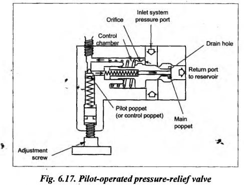
COMPOUND (OR PILOT-OPERATED) PRESSURE RELIEF VALVE The compound pressure relief valve overcomes the problem of direct-acting pressure relief valve. Thus these relief valves can be employed for a larger flow rate and higher system pressure. These valves are built in two stages. The construction of a typical sliding-spool type pilot-operated pressure relief valve is illustrated in Fig.6.17. This compound relief valve operates in two stages: Stage 1: The first stage is the same as direct-acting type. As in the direct-acting type, the movable main poppet allows fluid to escape to the reservoir when the system pressure exceeds the setting of the valve. This first stage is shown on the right side of the valve. The main poppet is retained to its seal by a light spring. Stage 2: The second stage, also known as pilot stage, is located on the left side of the valve. It contains a pilot valve poppet (also known as control poppet) which is held against a seat by an adjustable strong spring. The pressure limit can be adjusted by using an adjustment screw. The inlet system pressure acts on both sides of the main poppet because of the small orifice shown in Fig.6.17. The fluid passes from the inlet port through the orifice to a control chamber where it acts on the main poppet to add to the spring force. The system pressure also acts on the pilot poppet as shown in Fig.6.17. When the system pressure exceeds the setting pressure of the main poppet, the poppet is pushed from its seat towards left. This forces the pressurised fluid on the left side to escape through the centrally drilled drain hole of the main poppet. This limits the pressure on the control chamber side. Due to the restricted flow through the orifice, the fluid cannot enter into the control chamber as quickly as the fluid leaves through the drain hole. Because of this, the pressure on the right side exceeds that on the left and the main poppet moves to the left. Thus it permits the fluid flow directly to the reservoir tank from the inlet port. When the pressure falls below the setting pressure, the main poppet retracts back to its original position again.1. Introduction
2. Construction and Operation
Hydraulics and Pneumatics: Unit II: Hydraulic Actuators and Control Components : Tag: : Introduction, Construction and Operation - compound (or pilot-operated) pressure relief valve
Related Topics
Related Subjects

Hydraulics and Pneumatics
ME3492 4th semester Mechanical Dept | 2021 Regulation | 4th Semester Mechanical Dept 2021 Regulation