Hydraulics and Pneumatics: Unit V: Trouble Shooting and Applications
components selection of hydraulic/pneumatic circuits
Trouble Shooting and Applications - Hydraulics and Pneumatics
The manufacturer's catalogue data required for component selection are presented below.
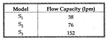
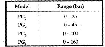
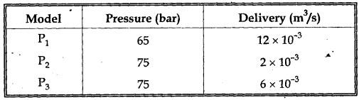
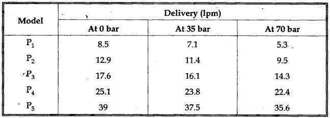
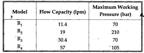
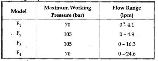
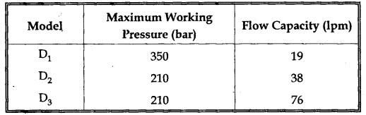
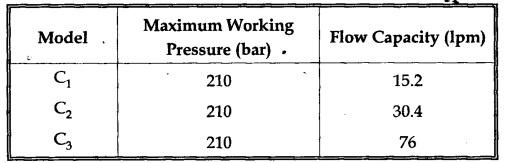
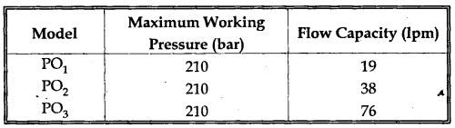
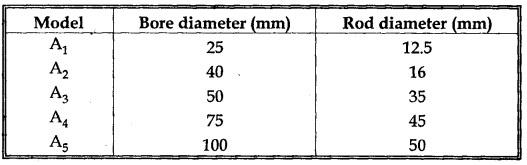
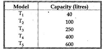
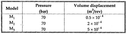
COMPONENTS SELECTION OF HYDRAULIC/PNEUMATIC CIRCUITS • From the manufacturer's catalogue, the various components (viz., suction strainer, pressure gauge, hydraulic pump, pressure relief valve, flow control valve, direction control valve, check valve, sequence valve, cylinder and oil reservoir) are selected based on the application requirements. • The manufacturer's catalogue data required for component selection are presented below. • The three models of suction strainer available are S1, S2 and S3 and are listed in Table 16.1. • The suction strainer can be selected based on the required capacity to pass the oil through it in litres per minute (1pm). Table 16.1. Suction strainer models • The various pressure gauge models available are listed in Table 16.2. Table 16.2. Pressure gauge models • Usually the pressure gauge model that provides the dial range twice the working pressure is selected. • The hydraulic pump is chosen based on (i) the delivery of pump, and (ii) the pressure to be generated. • The available hydraulic pump and vane pump models are listed in Tables 16.3 and 16.4 respectively. Table 16.3. Hydraulic pump models Table 16.4. Vane pump models • The pressure relief valve is chosen based on (i) the flow capacity and (ii) the maximum working pressure. • The pressure relief valve models available are listed in Table 16.5. Table 16.5. Pressure relief valve models • The flow control valve is chosen based on (i) the maximum working pressure and (ii) the flow range. • The flow control valve models are shown in Table 16.6. Table 16.6. Flow control valve models • The direction control valve is chosen based on (i) the maximum working pressure and (ii) the flow capacity. • The direction control valve models are shown in Table 16.7. Table 16.7. Direction control valve models • The check valve is chosen based on (i) the maximum working pressure and (ii) the flow capacity. • The check valve models are shown in Table 16.8. Table 16.8. Check valve models • The pilot-operated check valve is chosen based on (i) the maximum working pressure and (ii) the flow capacity. • The sequence valve models are shown in Table 16.9. Table 16.9. Pilot-operated check valve models/Sequence valve models • The cylinder is chosen based on the application requirement. • The various cylinder models for maximum working pressure of 210 bar are shown in Table 16.10. Table 16.10. Cylinder models • The oil reservoir is chosen based on its storage capacity required for the particular application. • By thumb rule, reservoir capacity should be 2 to 3 times the maximum flow rate. • The various oil reservoir models are shown in Table 16.11. Table 16.11. Oil reservoir models • A motor for a particular application is chosen based on the working pressure and volume displacement. • The three models available are shown in Table Table 16.12. Motor models Note In the selection from available component models, always the over-capacity model should be selected (instead of selecting near valued under-capacity model).1. Selection of Suction Strainer
2. Selection of Pressure Gauge
3. Hydraulic Pump
4. Selection of Pressure Relief Valve
5. Selection of Flow Control Valve
6. Selection of Direction Control Valve
7. Selection of Check Valve
8. Selection of Pilot-Operated Check Valve/Sequence Valve
9. Selection of Cylinder
10. Selection of Oil Reservoir
11. Selection of Motor
Hydraulics and Pneumatics: Unit V: Trouble Shooting and Applications : Tag: : Trouble Shooting and Applications - Hydraulics and Pneumatics - components selection of hydraulic/pneumatic circuits
Related Topics
Related Subjects

Hydraulics and Pneumatics
ME3492 4th semester Mechanical Dept | 2021 Regulation | 4th Semester Mechanical Dept 2021 Regulation