Manufacturing Technology: Unit IV: CNC Machines
compensations for machine accuracy
CNC Machines - Manufacturing Technology
Machine accuracy is the accuracy of the movement of the carriage and it is influenced by
COMPENSATIONS FOR MACHINE ACCURACY Machine accuracy is the accuracy of the movement of the carriage and it is influenced by (i) Geometric accuracy in the alignment of the slide ways (ii) Deflection of the bed due to load (iii) Temperature gradients on the machine (iv) Accuracy of the screw thread of any drive screw and the amount of backlash (lost motion) (v) Amount of twist (wind up) of the shaft which will influence the measurement of rotary transducers The CNC stems offer compensation for the various machines accuracy. These are detailed below: To compensate for movements of the machine slide due to in accuracy of the pitch along the length of the ball screw, pitch error compensation is required. To begin with, the pitch error curve for the entire length of the screw is built up by physical measurement with the aid of an external device (like laser) as shown in Figure 4.31. Then the required compensation at predetermined points is fed in to the system. Whenever a slide moves, this compensation is automatically added up by the CNC system. Whenever a slide is reversed, there is some lost motion due to backlash between nut and screw. Compensation is provided by the CNC system for the motion lost due to reversal, i.e. extra movement is added into the actual movement whenever the reversal takes place. This extra movement is equal to backlash between screw and nut. It has to be measured in advance and fed to the system. This value keeps on varying due to wear of ball screws. Hence, the compensation value has to be updated regularly from time to time. Inaccuracy due to sag in the slide can be compensated by the system. Compensations required along the length of the slide have to be physically measured and fed to the system. The system automatically adds up the compensation to the movement of the slide. Tool nose compensation normally used on tool for turning centers. While machining chamfers, angles or turning curves, it is necessary to make allowance for the tool tip radius, this allowance is known as radius compensation. As shown in Figure 4.32, if the allowance is not made, the edges of the tool tip radius would be positioned at the programmed X and Z coordinates and the tool will follow the path resulting in a taper produced which will be incorrect. In order to obtain correct taper, tool position has to be adjusted. It is essential that the radius at the tip of the tool is fed to the system to make an automatic adjustment on the position and movement of the tool to get the correct taper on the work. In Figure 4.32, the distance Xc and Yc are the adjustments necessary in X axis and Y axis respectively distance. The diameter of the used tool may be different from the actual value because of regrinding of the tool or due to non-availability of the assumed tool. It is possible to adjust the relative position of cutter size with respect to machine face and this adjustment is known as cutter diameter compensation.(i) Lead screw pitch error compensation:
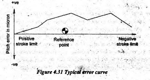
(ii) Backlash compensation:
(iii) Sag compensation:
(iv) Tool nose compensation:
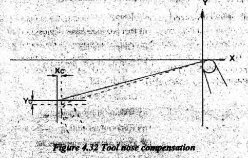
(v) Cutter diameter compensation:
Manufacturing Technology: Unit IV: CNC Machines : Tag: : CNC Machines - Manufacturing Technology - compensations for machine accuracy
Related Topics
Related Subjects

Manufacturing Technology
ME3493 4th semester Mechanical Dept | 2021 Regulation | 4th Semester Mechanical Dept 2021 Regulation