Theory of Machines: Unit II: Gears and Gear Trains
Classification of Gears
Gears and Gear Trains - Theory of Machines
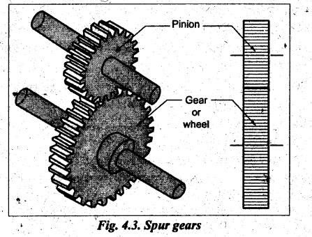
Spur gears are simple in construction, easy to manufacture and less costly.
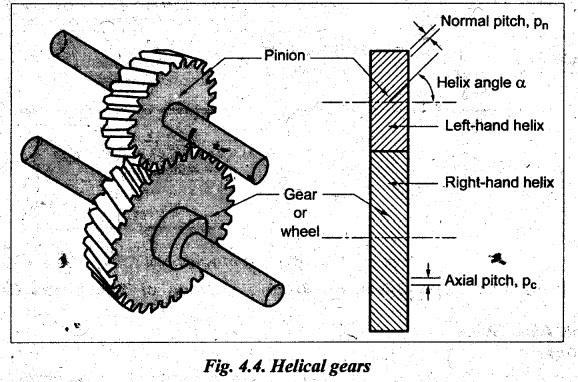
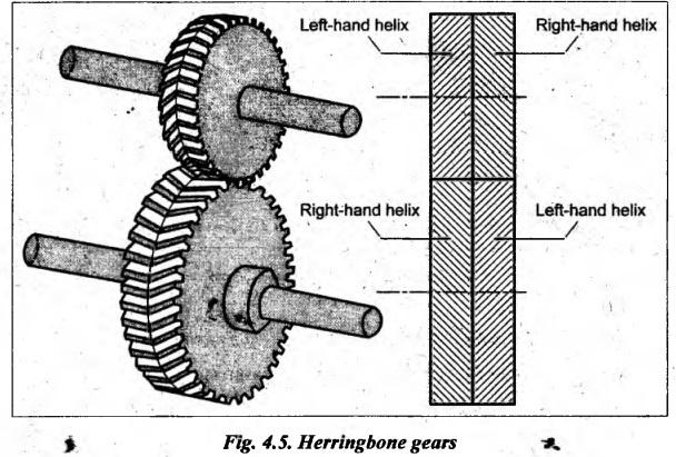
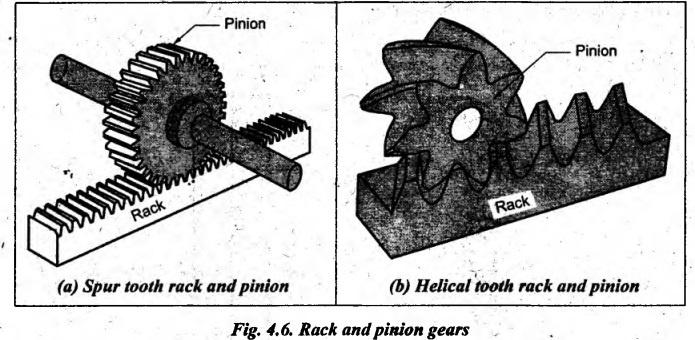
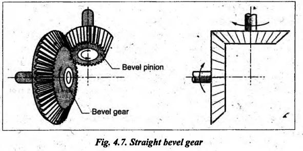
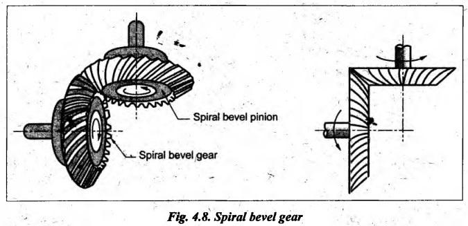
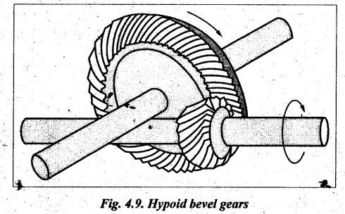
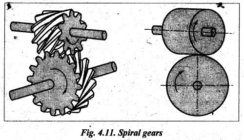
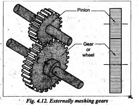
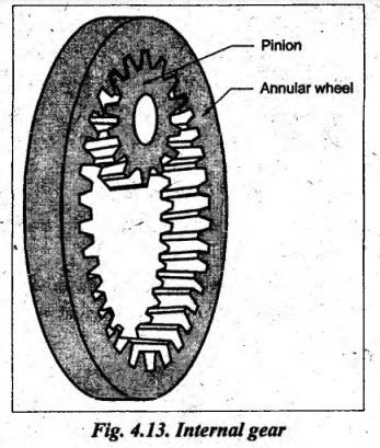
CLASSIFICATION OF GEARS Gears are classified in different ways, as shown in Fig.4.2. A. Parallel Axes Gears 1. Spur Gears • Spur gears have teeth parallel to the axis of rotation and are used for transmitting motion between two parallel shafts, as shown in Fig.4.3. • Advantages: (i) Spur gears are simple in construction, easy to manufacture and less costly. (ii) They have highest efficiency and excellent precision rating. • Applications: They are used in high-speed and high-load applications in all types of gear trains. 2. Helical Gears • Helical gears have teeth inclined to the axis of rotation and are used for transmitting motion between two parallel shafts, as shown in Fig.4.4. • Advantages: (i) Helical gears operate smoother and quieter than spur gears because of gradual engagement of the teeth during meshing and increased contact ratio. (ii) For the same width, teeth of helical gears are longer than spur gears; hence helical gears have a greater load carrying capacity. • Applications: Because of smoother action, the helical gears are preferred in high-speed and high-load applications such as automobiles and turbines. • Drawback: Since the teeth are inclined to the axis of rotation, helical gears are subjected to axial thrust loads and bending couples. Note • Axial circular pitch (Pc) and normal circular pitch (Pn): • Axial circular pitch (Pc) is the distance between the corresponding points on adjacent teeth measured parallel to the axis (Fig.4.4), • Normal circular pitch (Pn) is the distance between the corresponding points on adjacent teeth measured along the pitch circle in normal plane (Fig.4.4). 3. Herringbone (or Double Helical) Gears • Herringbone gears, also known as double helical gears, consists of teeth having a right and left handed helix cut on the same blank, as shown in Fig.4.5. • Advantage: The drawback of helical gears (that is, the problem of axial thrust) is eliminated by herringbone gears. In herringbone gears, two axial thrusts oppose each other and nullify, hence the shaft is free from any axial force. • Drawback: Though the herringbone gears have high load carrying capacity, they are more costlier than single helical gear. • Applications: Herringbone gears are limited to high load carrying capacity applications such as in cement mills and crushers. 4. Rack and Pinion Gears • Rack is a segment of a gear of infinite diameter. • When a straight line gear (called rack) meshes with the circular wheel (called pinion), then the combination so formed is called rack and pinion arrangement. • The rack and pinion arrangement is illustrated in Fig.4.6. • The tooth of a rack can be spur (Fig.4.6(a)) or helical (Fig.4.6(b)). • The rack and pinion is used to convert rotary motion into translatory motion or vice - versa. • Application: The use of rack and pinion can be found in lathes where rack gives motion to saddle. • Bevel gears are used to transmit power between two intersecting shafts. • The bevel gears are formed by cutting teeth along the elements of frustrum of a cone. • The bevel gears are mounted on intersecting shaft at any angle, although 90° shaft angle is most common • The two types of bevel gears are: 1. Straight bevel gears, and 2. Spiral bevel gears. 1. Straight Bevel Gears • If the teeth on the bevel gears are parallel to the lines generating the pitch cones, then they are called straight bevel gears, as shown in Fig.4.7. • Usually, the straight bevel gears are used to connect at right angles which run at low speeds. • Mitre gears: When two straight bevel gears of same size connect two shafts at right angles to each other, the gears are called mitre gears. • Advantage: The straight bevel gears can operate under high speeds and high loads. • Drawback: Straight bevel gears are noisier in operation at higher pitch line velocities. • Applications: The bevel gears can be found in automobile differentials, blenders and conveyors. 2. Spiral Bevel Gears • When the teeth of a bevel gear are inclined at an angle to the face of the bevel, they are known as spiral bevel gears, as shown in Fig.4.8. • Advantages: (1) Because of the spiral tooth, the contact length and contact ratio are more. (ii) They are smoother in action and quieter than straight tooth bevels as there is gradual load application and low impact stresses. • Drawback: The efficiency is slightly lower than straight bevel gears. • Applications: The spiral bevel gears find applications in drive to the differential of an automobile. • The skewed axes gears are used to connect two non-parallel and non-intersecting shafts. • The three important skewed axes gears are: 1. Hypoid bevel gears, 2. Worm and worm wheel, and 3. Spiral (or crossed helical) gears. 1. Hypoid Bevel Gears • Hypoid bevel gears, also known as hypoid gears, are used for right angle in which the axes do no intersect. • Hypoid gears are similar in appearance to spiral-bevel gears, but the axis of pinion is offset from the axis of the gear, as shown in Fig.4.9. • These gears are called hypoid gears because their pitch surfaces are hyperboloids of revolution. • Advantages: They operate more smoothly and quietly than spiral bevel gears. • Applications: In general, the hypoid gears are most desirable for those applications involving large speed reduction ratio. These gears are widely used in present automobile drive line power transmission. 2. Worm and Worm Wheel • Worm and worm wheel, also known as worm gears, s. are used to transmit power from one shaft to another which are non-intersecting and their axes are normally right angles to each other. • Worm and worm gear pair consists of (i) a worm, which is very similar to a screw, and (ii) a worm gear, which is a helical gear, as shown in Fig.4.10. • Advantages: (i) The worm gears can be used for high speed reductions upto 400 : 1, (ii) The operation is smooth and quiet. (iii) The worm gear drives are irreversible. It means that the motion cannot be transmitted from worm wheel to the worm. This property of irreversible is advantageous in load hoisting applications like cranes and lifts. • Drawbacks: (i) The efficiency is low and they are costly. (ii) The power transmitting capacity is also low. (iii) Since sliding occurs, the amount of heat generation is quite high. • Applications: Worm gear drives are widely used as a speed reducer in materials handling equipment, machine tools and automobiles. 3. Spiral (or Crossed Helical) Gears • Spiral gears, also known as crossed helical gears or skew gears, are used to transmit power between two non-intersecting non-parallel shafts. • The arrangement of spiral gears is illustrated in Fig.4.11. • The teeth of crossed helical gears have a point contact with each other, therefore they are used for light load and low load applications. • Applications: The spiral gears find applications in the drive for feed mechanisms on machine tools, car-shafts and oil pumps on small IC engines. 1. External (or Externally Meshing) Gears • In external gears, the teeth of gears mesh externally with each other, as shown in Fig.4.12. • In any pair of external gears, the smaller one is called pinion and the larger one is called gear or wheel. • The external gears rotate in opposite directions. 2. Internal (or Internally Meshing) Gears • In internal gears, the teeth of gears mesh internally with each other, as shown in Fig.4.13. • In any pair of internal gears, the smaller one is called pinion and the larger one is called annular wheel. • The internal gears rotate in same direction. • Applications: Planetary gear drive of high speed reduction ratios, clutches, etc.
I. Classification of Gears Based on Relative Position of Two Shafts Carrying Gears
B. Intersecting Axes Gears
C. Non-parallel and Non-intersecting Axes Gears (or Skewed Axes Gears)

II. Classification of Gears Based on the Type of Meshing of Gears
Theory of Machines: Unit II: Gears and Gear Trains : Tag: : Gears and Gear Trains - Theory of Machines - Classification of Gears
Related Topics
Related Subjects

Theory of Machines
ME3491 4th semester Mechanical Dept | 2021 Regulation | 4th Semester Mechanical Dept 2021 Regulation