Manufacturing Processes: Unit III: Bulk Deformation Processes
Classification of drawing
Mechanical Deformation Processes
According to the application of drawing process, the drawing are classified as
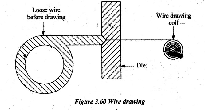
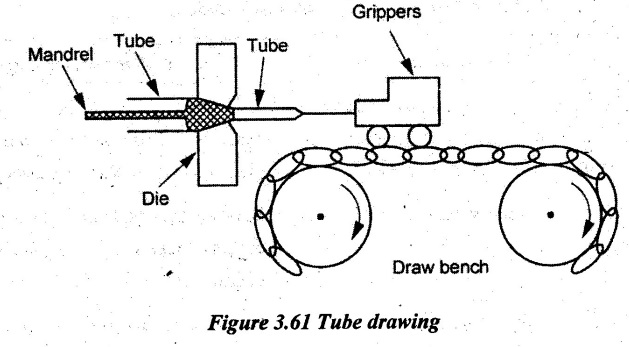
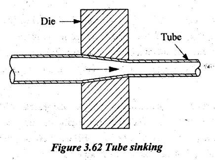
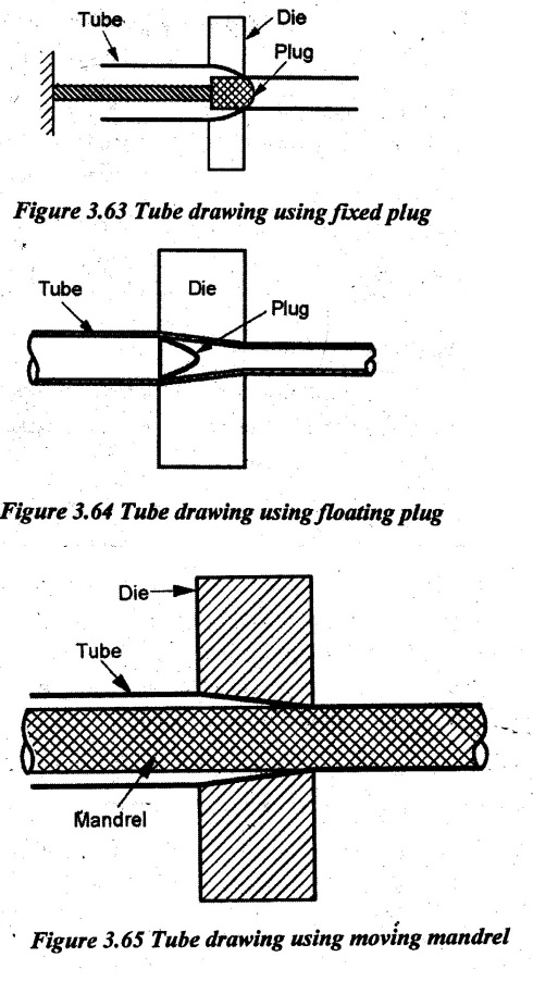
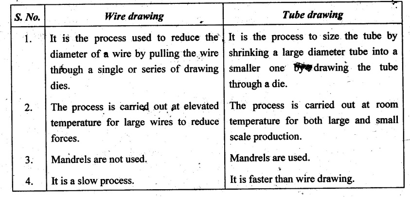
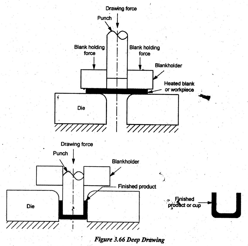
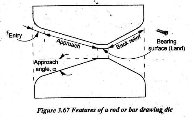
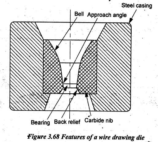
CLASSIFICATION OF DRAWING According to the application of drawing process, the drawing are classified as 1. Wire drawing 2. Rod drawing 3. Tube drawing 4. Deep drawing. Wire drawing is used for producing wires e.g. electrical wires, cables, strings, welding electrodes, fencing etc. Wire is a drawn product having less than 5 mm diameter. Wire drawing is usually done in multiple steps using 4 to 12 dies because the length of the wire drawn is too long, often several meters. Wire drawing is a continuous process. Initially, the point of wire is sized. So, it is freely entered into the die. Tungsten carbide dies are used for drawing hard wires and diamond dies is the choice for fine wires. This sized point coming out of the die orifice is fixed on the pliers or carriage which pulls the rod through all zones of the die orifice. It reduces the diameter of the rod. Drawing speeds can be as high as 30 m/s. For making fine wire, the rod is passed through the number of dies. Each die provides a small reduction. So, the desired total reduction is achieved by the series of dies. In this case, annealing is sometimes required between dies to relieve work hardening. Finally, the wire is connected to the power reel to get the wire coil. The basic difference between bar or rod drawing and wire drawing is the large size of bar stock used for bar drawing. In rod drawing, the rod which is to be drawn should be straight and the maximum length of the rod drawn is depending on the carriage movement. The drawing speed varies rod to rod depending on the size of the rod. A draw bench is used for drawing of rods, bars and tubes because rods and bars cannot be coiled. The process consists of placing the hot drawn bar through a die in which the bore size confirms to the finished size of product. Bar drawing is done in a single draft. Draft is the difference between initial and final diameter. Drawn rods are used as raw materials for making bolts, nails, screws, rivets and springs whereas the drawn metal bars are used for machining, forging and other processes. Draw speeds can be as high as 1500 mm/s. Maximum reduction in cross-sectional area per pass of drawing is restricted to 45%. Beyond this reduction, tensile stress may increase and surface finish may become poor. Step 1: Coating: The surface of the bar or coil is coated with a drawing lubricant to aid cold drawing. Soap solution or oil is used as lubricant. Step 2: Pointing: The die opening is always smaller than the original bar or coil section size. Therefore, several cm of the lead end of the bar or coil are reduced in size by swaging or extruding so that it can freely pass through the drawing die. Step 3: Cold drawing: In this process, the material being drawn is at room temperature. The pointed end of the bar or coil is passed through the die where it enters a gripping device of the drawing machine. The drawing machine pulls or draws the remaining unreduced section of the bar or coil through the die. The die reduces the cross section of the original bar or coil, shapes the profile of the product and increases the length of the original bar or coil. Step 4: Finished product: The drawn product displays a bright and/or polished finish, increased mechanical properties, improved machining characteristics, precise and uniform dimensional tolerances. Step 5: Multi-pass drawing: The cold drawing of complex shapes/profiles may require that each bar/coil be drawn several times in order to produce the desired shape and tolerances. This process is called multi-pass drawing and involves drawing through smaller and smaller die openings. Material is generally annealed between each drawing pass to remove cold work and increase ductility. Step 6: Annealing: It is a heat treatment process generally used to soften the material being drawn, modify the microstructure, mechanical properties and machining characteristics and/or remove internal stresses in the product. Depending on the desired characteristics of the finished product, annealing may be used before, during (between passes) or after the cold drawing operation depending on material requirements. Tube Drawing Tube drawing is similar to bar drawing except the beginning stock is a tube. In tube drawing, cylinders and tubes which are made by extrusion process are finished by drawing process. It is used to decrease the diameter, reduce wall thickness, improve the surface finish and improve dimensional accuracy, The cross section can be circular, square hexagonal or in any shapes. A mandrel may or may not be used depending on the specific process used. The function of the mandrel is to assist in wall reduction and control the size of the hole. However, the mandrel may be omitted if it is not necessary to make a reduction in the wall thickness or if the dimensions and surface of the inside are not important. The process of tube drawing is shown in Figure 5.61. This procedure of tube drawing is similar to rod drawing but it usually requires a mandrel of the requisite diameter to form the internal hole. Tubes as large as 0.3 m in diameter can be drawn. Tube drawing can be carried out by several methods. Tube drawing is classified into the following types: 1. Tube sinking 52. Tube drawing with fixed plug 3. Tube drawing with floating plug, and 4. Tube drawing with moving mandrel. The process to draw a pipe without any mandrel or plug is known as tube sinking. In this process, only the outer diameter of the tube is reduced. The surface finish on inner diameter may not be good. Figure 3.62 shows the tube sinking process. For reducing the diameter of the tube precisely with good surface finish, the other three processes i.e., tube drawing with fixed plug, tube drawing with floating plug and tube drawing with moving mandrels are used. In mandrel or plug drawing, the mandrel is placed in the tube and the pull is given to the tube. In this method, both internal and external surfaces of the tube are controlled and the dimensional accuracy is good when compared to other methods. In this process, the plug may be fixed or floating type. The friction generated in fixed plug arrangement is more than floating plug and drawing load is high in fixed plug and it is less in floating plug In drawing tubes over a stationary mandrel as shown in Figure 3.63, the maximum practical sectional area reduction does not exceed 40% per pass. If a carefully matched mandrel/plug floats in the die throat of the die as shown in Figure 3.64, it is possible to achieve a reduction in area of 45%. This style is called drawing with floating plug. Problems with friction in tube drawing are minimized in drawing with a long mandrel or moving mandrel as shown in Figure 3.65. The mandrel consists of a long hard rod or wire that extends over the entire length of the tube and it is drawn through the die with the tube. In this design, the area reduction can be 50%. Howeyer, after drawing, the mandrel must be removed from the tube by rolling (reeling) which increases the tube diameter slightly and disturbs the dimensional tolerances. Deep drawing or sheet drawing is a metal forming process in which the sheet metal is stretched into the desired part shape. This process is used to make cup-shaped, box-shaped or other complex-curved hollow-shaped parts. The working principle of this process is that the metal blank is initially heated to a plastic state and placed on the die or cavity. Then, the forces are given by using the punch. So, the required shape of cup according to the shape of cavity is produced. The tensile forces applied to the sheet cause it to plastically deform into a cup-shaped part. Figure 3.66 illustrates the deep drawing process. This process requires a blank, blank holder, punch and die. The blank is a piece of sheet metal, typically a disc or rectangle, which is pre-cut from stock material and it will be formed into the part. The blank is clamped down by the blank holder over the die which has a cavity in the external shape of the part. A tool called a punch moves downward into the blank and draws or stretches the material into the die cavity. Both die and punch experience wear from the forces applied to the sheet metal. Therefore, they are made from tool steel or carbon steel. After a part is completely drawn, the punch and blank holder can be raised and the part is removed from the die. The portion of the sheet metal that was clamped under the blank holder may form a flange around the part that can be trimmed off. Deep drawing is most effective with ductile metals such as aluminum, brass, copper mild steel. Examples of parts formed with deep drawing include automotive bodies and fuel tanks, beverage cans, cups, kitchen sinks, pots and pans. Drawing die which is used for rod or bar drawing is shown in Figure 3.67. It is usually made of tool steels or cemented carbides. It has the following features: ● Entry region: It is a funnel-shaped entry of the die which provides lubricant into the die to prevent scoring of work and die. ● Approach: It is a cone-shaped region where the drawing occurs. ● Bearing surface: It is a region that determines the final stock size. ● Back relief: It is an exit zone that is provided with a back relief angle (half-angle) of about 30°. Wire drawing die is shown in Figure 3.67. It has the following features: ● Bell: Shape of the bell causes the hydrostatic pressure to increase and promotes the flow of lubricant into the die. ● Approach angle: The approach angle is where the actual reduction in diameter occurs. It is half of the die angle a. ● Bearing surface: The bearing region produces a frictional drag on the wire and also removes the surface damage due to die wear without changing dimensions. ● Nib: The die nib is made from cemented carbide or diamond and it is encased for protection in a thick steel casing. ● Back relief: The back relief allows the metal to expand slightly as the wire leaves the die and also minimises abrasion if the drawing stops or the die is out of alignment.1. Wire Drawing
2. Rod Drawing
3. Rod and Wire Drawing Process
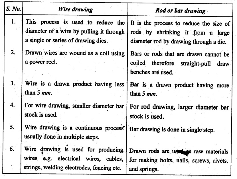
4. Difference between Wire Drawing and Rod Drawing
6. Difference between Wire Drawing and Tube Drawing
7. Deep Drawing or Sheet Drawing
8. Features of a Drawing Die
Manufacturing Processes: Unit III: Bulk Deformation Processes : Tag: : Mechanical Deformation Processes - Classification of drawing
Related Topics
Related Subjects
Manufacturing Processes
ME3393 3rd semester Mechanical Dept | 2021 Regulation | 3rd Semester Mechanical Dept 2021 Regulation