Theory of Machines: Unit I: Kinematics of Mechanisms
classification of cams and followers
Kinematics of Mechanisms - Theory of Machines
In the above types of cams, the radial cams are the most commonly used in many industrial applications.
CLASSIFICATION OF CAMS AND FOLLOWERS
1. Classification of Cams
• The cams can be classified according
to their shape as
1. Radial (or disc or
plate) cams,
2. Wedge (or flat)
cams,
3. Cylindrical (or
barrel) cams,
4. Conical cams,
5. Globoidal cams, and
6. End (or face) cams.
• In the above types of cams, the
radial cams are the most commonly used in many industrial applications. Due
to this practical importance, the most of the discussions in this chapter are
devoted to the study of radial cams.
1. Radial (or Disc or Plate) Cams
• In radial cams, the follower
reciprocates (i.e., translates) in a plane perpendicular to the axis of cam,
as shown in Fig.3.1.
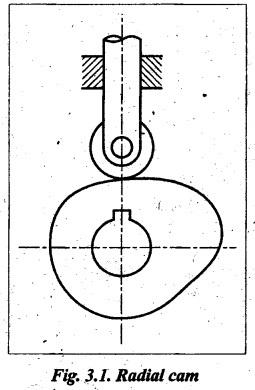
• The radial cams are also known as disc
cams or plate cams (as these cams are made from thicker
plates).
• In actual practice, the radial cams
are widely used due to their simplicity and compactness.
2. Wedge (or Flat) Cams
• A wedge cam has wedge shape which
imparts translatory motion to the follower, as shown in Fig.3.2.
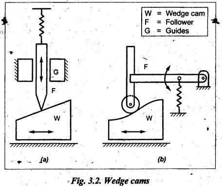
• As shown in Fig.3.2, the wedge 'W' do
not rotate, it only translates in forward and. backward directions. But the
follower 'F' may have translatory motion (Fig.3.2(a)) or oscillatory
motion (Fig.3.2(b)).
• To maintain the contact between the
cam ad the follower, springs are used.
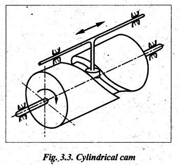
3. Cylindrical (or Barrel or Drum) Cams
• In a cylindrical cam, a cylinder
which has a circumferential contour cut in the surface, rotates about its axis.
The follower rides at the groove cut on the periphery of the cylinder.
• In 'these types of cams, the follower
either reciprocates (or oscillates) in a plane parallel to the axis of the cam,
as shown in Fig.3.3.
• The cylindrical cams are also known
as barrel cams or drum cams.
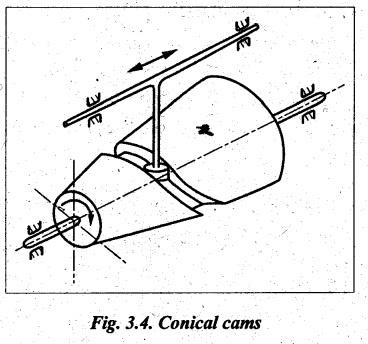
4. Conical Cams
• If the cylindrical surface in the
cylindrical cam is replaced by a conical surface, a conical cam is obtained.
• In conical cams, the follower rides
along a cut on the conical groove surface, as shown in Fig.3.4. In this, the
follower reciprocates in a direction parallel to an end-generator.
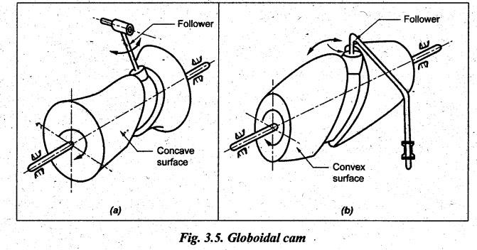
5. Globoidal Cams
• Globoidal cams are similar to the
cylindrical cams, but they have either a convex surface or a concave surface,
as shown in Figs.3.5(a) and (b).
• The circumferential contour is cut on
the surface of the cam and the cam imparts motion to the follower by rotating
about its axis.
• The globoidal cams have compact structure,
high load capacity, low noise and vibrations, and high reliability. Hence they
are widely used in industries.
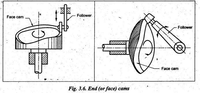
6. End (or Face) Cams
• The end cam has a rotating portion of
a cylinder, a cone, or a sphere, which oscillates a follower having its axis
perpendicular to the cam axis, as shown in Fig.3.6.
• In end cam, the follower translates
or oscillates, whereas the cam usually rotates.
• These cams are rarely used because of
the cost and the difficulty in cutting their contours.
2. Classification of Followers
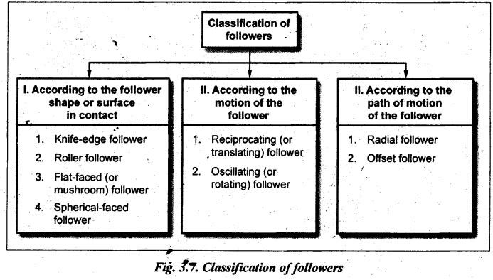
I. Classification according to the Follower Shape
1. Knife-Edge Follower
• When contacting end of the follower
has a sharp knife-edge, as shown in Fig.3.8(a), it
is called a knife-edge follower.
• The knife-edge follower is rarely
used because of excessive wear due to small area of contact.
• Also, in this follower, a
considerable thrust exists between the follower and guide.
2. Roller Follower
• When contacting end of the follower
is a roller, as shown in Fig.3.8(b), it is called a roller follower.
• In roller followers, the wear rate is
considerably reduced (than that of the knife-edge follower) because of rolling
motion between contacting surfaces.
• In roller followers, the side thrust
between the follower and the guide is lesser than that of the knife-edge
follower.
• The roller followers, are commonly
used where more space is available such as in large stationary gas or oil
engines, aircraft engines and in production machinery.
3. Flat-Faced (or Mushroom) Follower
• When contacting end of the follower
is perfectly flat faced, as shown in Fig.3.8(c), it
is called a flat-faced follower.
• In this follower, the thrust at the
bearing is less as compared to knife-edge and roller followers.
• The flat-faced follower causes high
surface stresses.
• The flat-faced followers are
commonly used in automobile engines.
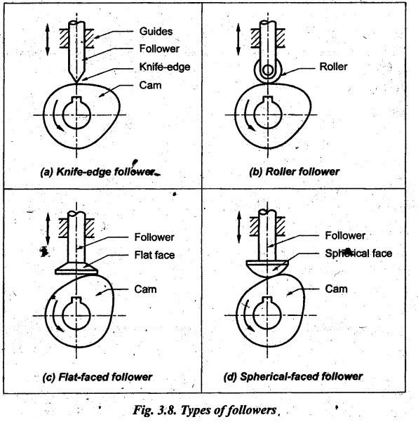
4. Spherical-Faced Follower
• When contacting end of the follower
is of spherical shape, as shown in Fig.3.8(d), it
is called a spherical-faced follower.
• In order to minimise the surface
stresses produced in flat-faced follower, the flat end of follower is machined
to a spherical shape.
• Thus the spherical-faced follower is
preferred to flat-faced follower as there is less surface stress and wear in
the spherical-faced follower.
• The spherical-faced followers are
also widely used in automobile engines.
II. Classification according to the Motion of Follower
1. Reciprocating (or Translating) Follower
• When the follower reciprocates in
guides as the cam rotates uniformly, it is known as reciprocating or
translating followers.
• The followers shown in Figs.3.8(a) to
(d) and Fig.3.9(a) are all reciprocating followers.
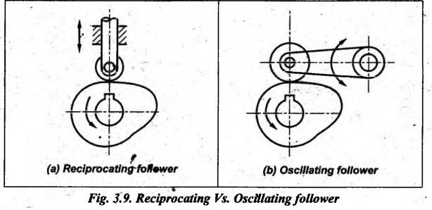
2. Oscillating (or Rolling) Follower
• When the uniform rotary motion of
the cam is converted into predetermined oscillatory motion of the follower, it
is called oscillating or rotating follower.
• The followers shown in Figs.3.2(b)
and 3.9(b) are typical oscillating followers.
III. Classification according to the Path of Motion of the
Follower
1. Radial (or In-line) Follower
• When the motion of the follower is
along an axis passing through the centre of the cam, it is known as radial or
in-line follower.
• The followers shown in Figs.3.8(a) to
(e) and Fig.3.10(a) are all radial followers.
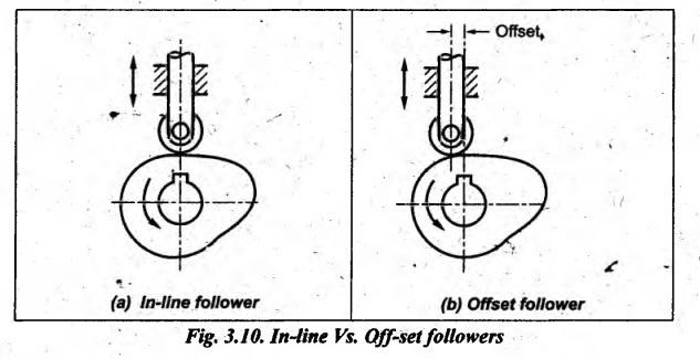
2. Offset Follower
• When the motion of the follower is
along an axis away (offset) from the axis of the cam centre, it is called
offset follower.
• The amount of offset is the distance
between these two centre lines.
• A typical offset follower is shown in
Fig.3.10(b).
• An offset is usually provided on a
side (so as to decrease pressure angle at the point of maximum velocity during
outstroke) in order to reduce the side thrust in guides of followers.
Theory of Machines: Unit I: Kinematics of Mechanisms : Tag: : Kinematics of Mechanisms - Theory of Machines - classification of cams and followers
Related Topics
Related Subjects

Theory of Machines
ME3491 4th semester Mechanical Dept | 2021 Regulation | 4th Semester Mechanical Dept 2021 Regulation