Manufacturing Technology: Unit II: Turning Machines
capstan and turret lathes
Turning Machines - Manufacturing Technology
Capstan and turret lathes are the natural developments of a centre lathe.
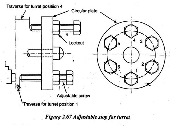
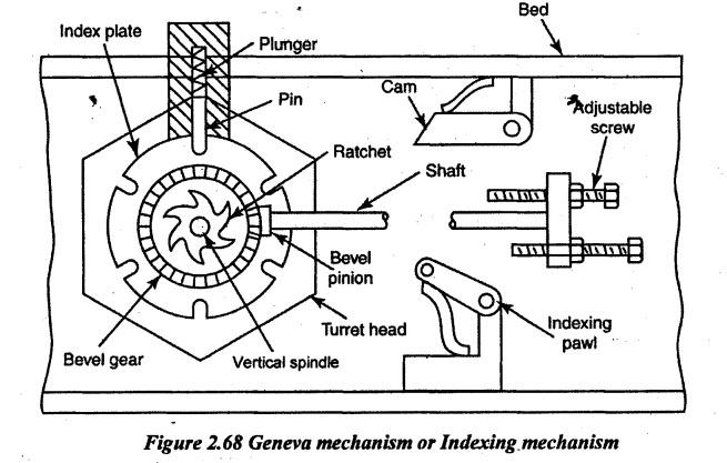
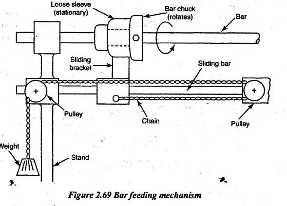
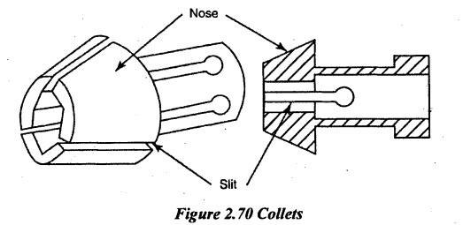
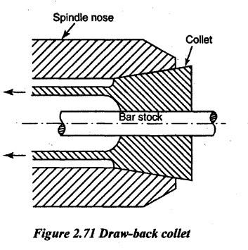
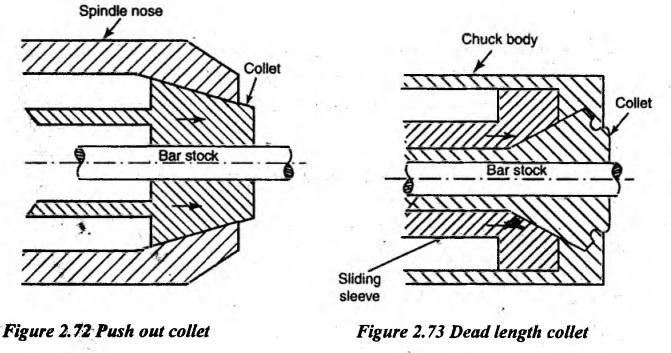
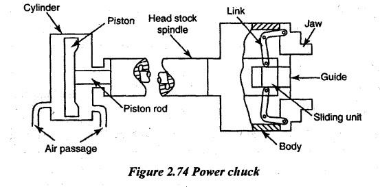
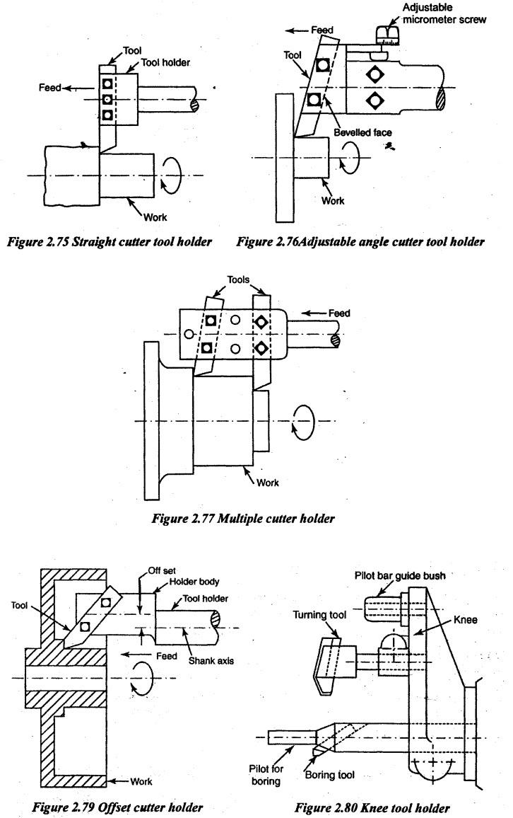
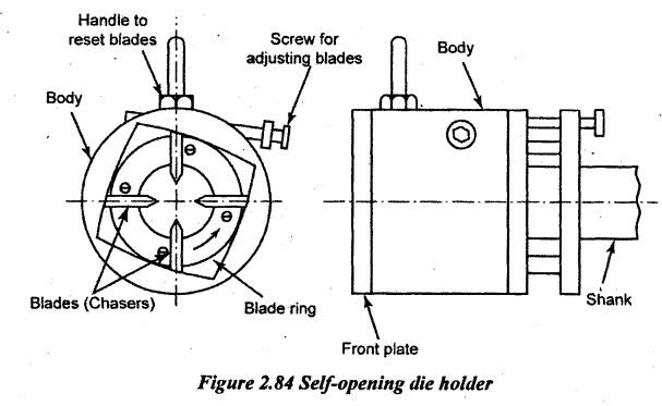
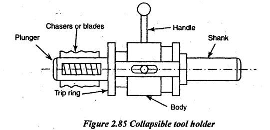
CAPSTAN AND TURRET LATHES Capstan and turret lathes are the natural developments of a centre lathe. These lathes are built to machine workpieces that are large in number and on repetitive basis i.e. for batch production jobs). The construction and working principle of both lathes are similar to each other. But they differ in applications. The turret lathe is used for heavy jobs whereas the capstan lathe is used for light and small jobs. Capstan and turret lathes bridge the gap between the slow working centre lathe and fully automatic lathes specifically designed for mass production of very high production rates. In contrast to centre lathes, capstan and turret lathes are semi-automatic. The main distinguishing feature of these lathes is the axially movable and indexable hexagonal turret or capstan head in place of the tailstock. The turret or capstan is a multiple tool holder which enables presetting of all the tools required for performing various operations on the job. The turret holds a large number of cutting tools. It allows for mounting six tool block, each one of which can contain one or more tools depending upon the requirement. Further, on the cross slide, two tool posts are mounted in which one is at the front tool post and the other is on the rear tool post. Each one of them can hold up to four tools each. Thus, the total carrying capacity is a maximum of 14 tools when only one tool is mounted in each of the locations. The turret is indexed automatically and each tool may be brought in line with the lathe axis in a regular sequence. Workpieces are held in collets or chucks mounted on the headstock. The longitudinal and cross feed movements of the turret saddle and cross slide are controlled by the adjustable stops. This feature enables the different tools set at different stations to move a preset amount for performing various machining operations on identical workpieces without measuring the dimensions of the machined surface in each case. These lathes are more productive for quick engagement and overlapped functioning of the tools in addition to faster mounting and feeding of the job and rapid speed change. These lathes enable the repetitive production of same job requiring less involvement, effort and attention of the operator for pre-setting the work for speed and feed rate and length of travel of the cutting tools. However, these lathes are costlier and hence, it is more suitable and economically viable for batch production or small lot production. The principal parts of the capstan and turret lathes are as follows. 1. Bed 2. Headstock 3. Turret head and saddle 4. Cross slide. 1. Bed: Bed is the base part of the lathe. It is a box type which is made of cast iron. Guide ways on the top of the bed have accurately been provided. The headstock is mounted on one end of the bed. The other end carries saddle and the turret is mounted on it. The cross slide is mounted on the bed in between the turret head and headstock. The bed should be strong and rigid to withstand heavy loads, force and vibrations during machining. 2. Headstock: The headstock of capstan and turret lathe is similar to a head in ordinary centre lathe but it is larger and heavier in construction to house the spindle and driving mechanisms. One of the main features of this headstock is the provision for rapid stopping, starting and speed changing. It helps in the rapid selection of required cutting speed and at the same time to minimize the loss of time in speed changing, stopping and starting. A powerful motor of 30 to 2000 rpm speeds is fitted. The four main types of headstock are as follows. (i) Back geared or Step cone pulley driven headstock (ii) Direct electric motor driven headstock (iii) All geared headstock (iv) Pre-selective stock. Step cone pulley driven headstock and all geared headstock are same as the one already discussed in centre lathe on Chapters 2.6.1 and 2.6.2 on Pages 2.11 and 2.12 respectively. Direct electric motor driven headstock: In this type of headstock, the spindle of the lathe and the armature shaft of the motor are one and the sante. It is mounted with a variable speed electric motor. With three or four speeds, the lathe is suitable for small diameter works rotated at high speed during working. Different spindle speeds are obtained by controlling the motor regulator. Pre-selective headstock: In this type, an all geared headstock is provided with friction clutches. Rapid stopping, starting and speed changing for different machining operations can be done by simply pushing a button or pulling a lever. The required speed of the next operation can also be selected in advance. At the end of the first operation, the lever is actuated to rotate the spindle at the selected speed without stopping the machine. 3. Turret head and saddle: In a capstan lathe, the turret head is mounted on a ram which slides on a saddle. It can be positioned on lathe bed ways and clamped well. The turret head is mounted on the ram fitted on a saddle which in turn it is sliding on the bed as shown in Figure 2.65. The turret head slides longitudinally on a saddle. The ram is actuated either by hand or power. The forward movement of the ram is controlled by a preset or adjustable stop screw. In a turret lathe, the turret head is mounted on the saddle itself which slides on the bed ways during machining as shown in Figure 2.66. A turret head has a hexagonal block having six faces with a bore for mounting six or more than six tools at a time. The four threaded holes on these faces are used to accommodate tool holders. The different tools are brought to the machining position by indexing i.e. rotated through a fixed angle. The turret can be indexed about a vertical axis. Each tool is indexed through 60° by the rotation of a circular plate. The circular plate is automatically indexed along with the turret head. Bringing the next tool into the cutting position is done by a mechanism called Geneva mechanism. There are 6 adjustable stops i.e. adjustable screws on the circular plate, one for each of the six turret faces as shown in Figure 2.67. These stops can be preset depending on the requirement. While setting the tool, each stop is adjusted to control the length of travel of the turret. These preset stops are getting indexed when the turret is indexed. The tool post can move both in perpendicular and parallel directions to the spindle axis. Mostly, the power feed is used for the movement of the tool post. In the rear tool post, the parting-off tool is clamped in inverted position to make the direction of rotation of workpiece anticlockwise with respect to tool movement. 4. Cross slide: The two types of cross slides are as follows. 1. Reach over type 2. Side hung type (i) Reach over type: It is mounted on bed guide ways in between headstock and turret and also supported by a lower rail. The cross slide has two tool posts. One is at the front end having four faces of square turret for mounting tools. Each tool can be indexed by 90°. Stop bars are provided for controlling the motion of each tool which can automatically be indexed along with the square turret for the next machining operation. The tool post can move both in perpendicular_and parallel directions to the spindle axis. Mostly, the power feed is used for movement of the tool post. In the rear tool post, the parting-off tool is clamped in an inverted position to make the direction of rotation of workpiece anticlockwise with respect to tool movement. (ii) Side hung type: In this type of cross slide, the carriage does not extend across the entire top of the bed but it is entirely supported on the front way which has no rear tool post. It provides a greater swing capacity to accommodate large diameter workpiece. It is mainly used in turret lathe. However, this design has the disadvantage of lower rigidity which reduces the number of tools that can be used simultaneously. The turret is provided with automatic indexing mechanism. The Geneva mechanism as shown in Figure 2.68 is extensively used in turret lathes and automatic lathes. The Geneva mechanism is a mechanism that translates a continuous rotation into an intermittent rotary motion. Turret head, an index plate, a bevel gear and ratchet are mounted on the same vertical spindle of the saddle. A spring-actuated plunger is used to lock the index plate which prevents the rotation of turret during machining. When the turret trips the stop, the plunger is released with the help of a spring-loaded cam and a pin already fitted with the plunger. So, the index plate is free to rotate. Then, the indexing pawl is engaged with the ratchet and it ́rotates 1/6 or 60° of revolution. When the turret moves forward, the plunger is again locked the index plate. In turret and capstan lathes, the bar is automatically fed without stopping the lathe which reduces the production time. The bar stock passes through the chuck and hollow spindle of the lathe. The bar is fitted with the bar chuck by setscrews. The bar chuck rotates in a sleeve along with the bar. The loose sleeve is housed on a sliding bracket which slides over a sliding bar. It is again attached to one end of a chain as shown in Figure 2.69. A suspended weight is hanging at the other end of the chain to exert a constant force on the bar chuck towards the right. When the bar is released by the collet, the force due to weight will feed the work towards the right. It continues till the workpiece and it butts against the bar stop held in the turret. Then, the collet is closed. The workpieces are held in collets or chucks mounted on the headstock which may be operated either hydraulically or pneumatically. The large workpieces are held by means of chucks in turret lathes. In capstan lathes, the bar stock is held in collets. A bar feeding mechanism is used for automatic feeding the bar stock or workpiece. At least, six tools can be held on the hexagonal turret faces, four tools in front square tool post and one tool at the rear end. Generally, 1. Drilling, boring, reaming, counter boring, turning and threading tools are mounted on the hexagonal turret head. 2. Forming, chamfering, knurling and necking tools are mounted at the front end of the square turret. 3. Parting-off tool is mounted on the rear end of the square turret in an inverted or in a reversed position. The movement of the front and rear tool posts is controlled by pre-set stops. A bar stop is fitted at one end of the turret face which sets the required length of the workpiece by pushing when the collets are opened. Then, the bar or workpiece is tightly gripped by the collet. According to the order sequence of operations, the tool is moved. While machining the hexagonal turret head, it is moved in the forward direction. After completing each operation, the turret head automatically moves backward to index the tool along with adjustable stops. These stops control the forward movement of a turret. Mainly, the size of any capstan or turret lathe is specified by the maximum size of workpiece diameter, swing over cross slide and swing over bed. For example, if the size of a turret lathes is 80-150-225, the maximum size of workpiece diameter is 80mm, the swing over cross slide is 150 mm and the swing over bed is 225 mm. In addition to this, other specifications are listed below. 1. Number of spindle speeds. 2. Number of feeds for the carriage. 3. Number of feeds for the turret or saddle. 4. Net weight of the machine. 5. Floor space required. 6. Power of the motor required. 1. The production rate is high. 2. Heavier and larger workpiece chucking can be done. 3. It has a wider range of speeds. 4. Large number of tools can be held. 5. More than one operation can be performed at the same time. 6. It is more rigid. Hence, it withstands heavy cuts 7. Semi-skilled operators are enough 8. Labour cost is less. The work holding devices used on capstan and turret lathes are mostly automatic types. It reduces the setting time. Generally, the workpieces are held in collets, chucks or fixtures in turret lathes. 1. Collets: It is also called a collet chuck. The collet is mainly used to hold the bar stock of different sizes and shapes operated by either hand or power. The collet with a tapered nose has three or four equally spaced slits. Collets which are having springing action are called spring collets. The collet has a bore at its centre to receive the workpiece and the nose is made thicker for gripping the same. The bore may be of square, circular, hexagonal etc., depending on the shape and size of the work. The various types of collets are as follows. 1. Draw back collet 2. Push out collet 3. Dead length collet. Draw-Back collet: It is also called draw-in-collet. The taper of the collet is smoothly converged towards in (inward). The collect is fitted inside a taper portion of the spindle nose. A thrust tube provided behind the collet is used to move the collet in the spindle by moving axially either by a hand wheel or by a lever. This action clamps the bar stock by applying pressure on the collet and it axially pushes inward. So, the collet is pushed inward to clamp the workpiece or bar stock. Main disadvantage of draw-back collet: When the collet is pulled, the bar may be slightly moved inward. Due to this, the required length of the bar will be reduced. To compensate this error, the bar stock should be moved more than the required length. (ii) Push out collet: In a push out collet, the taper of the collet converges towards the right end (nose end). To clamp the bar stock, the collet is pushed into the tapered hole by the thrust tube which closes the jaws and grips the workpiece. To unclamp or release the workpiece from the collet, the collet will be pulled in. Main disadvantage of push out collet: During pushing out the collet, the workpiece may slightly move outward against the stop bar. Due to this, the length of the workpiece is slightly increased. To avoid this, an excess push out length should be compensated. (iii) Dead length collet: While gripping, the bar stock may move inward or outward in above two methods. This difficulty is rectified by providing a sliding sleeve in between spindle and collet. When the workpiece is clamped, the sleeve pushes through thrust tube by applying force on the collet. Thus, there is no axial movement either inward or outward. 2. Chucks: Chucks of three jaw, four jaw and magnetic chucks are already discussed in detail Chapter 2.8.1 on Page 2.17. Here, only power-operated chucks are discussed. (i) Power operated chucks: It is mainly used for holding heavy workpieces quickly with more gripping force. Power chucks are operated either by pneumatically (air-operated) or hydraulically. The air or hydraulic cylinder is fitted at the back of the headstock. A piston rod connects the piston and jaws by links which are actuated by sliding piston. When the compressed air is admitted to the right side of the piston, it moves left and jaws are moving inward to grip the workpiece. To release or unclamp the workpiece, the compressed air is admitted to the left side of the piston so that the piston moves right and jaws are moving out. The supply pressure of air is varied by a control valve. 3. Fixture: A specially designed member to locate and grip a workpiece is called fixture. It is mounted on the spindle by replacing a chuck or collet. The fixture is mainly used for machining a large number of identical pieces. If the specially designed fixture is used on lathes, it is called turning fixture which makes loading and unloading easy. To hold the tools in the respective positions, the various types of tool holders are fitted in a hexagonal turret or front tool post of the square turret or in the rear tool post. The following are the various types of tool holders. 1. Straight cutter tool holder 2. Adjustable angle cutter tool holder 3. Multiple cutter holders 4. Offset cutter holder 5. Sliding tool holder 6. Knee tool holder 7. Flange tool holder 8. Collet steady box tool holder 9. Combination tool holder 10. Self-opening type die holder 11. Knurling tool holder 12. Collapsible taps 13. Tap holder. (1) Straight cutter tool holder: Only one tool is held in this type of hole. It is also called simple tool holder. The shank of the tool holder is mounted on the turret face. Usually, the tool is held perpendicular to the shank axis. The holder is tightened with the tool bit by three setscrews to perform various operations. It may be fitted in multiple turning lead and knee tool holder. (2) Adjustable angle cutter tool holder: It is similar to a straight tool holder but having an angular slot as shown in Figure 2.76. The tool is fitted in this slot by means of setscrews. It helps in turning or boring operations which close the chuck jaws or to the shoulder of the workpiece. Multiple cutter holder: Two or more cutting tools can be held at a time in this type of tool holders as shown in Figure 2.77. Due to this, two or more operations can simultaneously be performed. It lowers the times of machining. Turning and chamfering tools can be fitted and used at the same time. (3) sliding tool holder: This type of tool holder is used for boring, recessing, grooving, facing etc. A slide is provided to adjust the holder up and down. The vertical adjustment is accurately done by a hand wheel having a micrometer dial as shown in Figure 2.78. The holder has two holes. The lower hole is aligned with the lathe axis for holding the boring tool, drilling tool and reaming tool. The upper hole is used for holding a turning tool. The down feed of the slide can be controlled by adjustable stops. (4) Offset Cutter Holder The holder body is offset with the shank axis as shown in Figure 2.79. By this offset, larger diameter works can be turned or bored. (5) Knee tool holder: A knee tool holder is mainly used for simultaneous turning and boring or turning and drilling operations. It has got a knee with three holes as shown in Figure 2.80. The lower hole coincides with the lathe axis for holding boring bars, drills etc. The top hole acts as a guide bush for the pilot bar projecting from the headstock. The central hole holds one turning tool. (6) Flange tool holder: In flange tool holder, the tool holder having a cylindrical bore is attached to a flange as shown in Figure 2.81 to bolt with the turret face. It can hold a boring bar, drills and reamers by means of a socket. Two setscrews are used for fixing the tools and sockets with the tool holder. (7) Roller steady box tool holder: It is commonly used for turning the bar stock. The tool is mounted on a slot by setscrews. Two rollers are provided on the opposite side of the cutter to give support to the work as shown in Figure 2.82. The roller takes up the cutting force during machining and it also prevents the bending of the machined portion. Due to the support of the workpiece, heavy cut and good surface finish are obtained by burnishing action of the roller. Rollers can be adjusted and the diameter of the workpiece can be reduced in one pass. The interference of chip may take place with the work. (8) Combination tool holder: It is a multiple turning head. The various types of tools can be arranged in the same tool holder itself. All these tools involve in cutting action at a time. For example, three turning tools and one boring bas are fitted in a single tool holder. The combination tool holder is directly fitted to the turret head through a flange. Outside bush and pilot bar are used to give an additional support while machining. Using a combination tool holder, the machining time of the work can be reduced by performing operations in the same cutting stroke. Figure 2.83 shows the schematic of combination tool holder. (9) Self-Opening die holder: This type tool holder is mainly used for cutting external threads accurately for a fixed length. It consists of four thread cutting blades called chasers as shown in Figure 2.84. These chasers are automatically opened after cutting the thread. The die holder consists of a shank, a body and a blade ring. The shank is connected to the body with the flange. The body with a bore can have an independent axial movement for a short distance. The blades are fitted in the radial slots of the blade ring. The size of the thread can be adjusted by adjusting the blade screw. The die head can be brought to the cutting position by using the reset handle. (10) Collapsible tap: Collapsible taps are specifically used for making internal threads. After cutting threads, the cutting edges of the tap collapse to reduce its overall diameter. So, the withdrawal of the tap will be easy without stopping the machine. The tap has a shank which is fitted on the turret face. A plunger having a taper at its end supports of the chaser during cutting. This plunger is again connected with a trip ring as shown in Figure 2.85. After completing the thread cutting, the trip ring butts against the rotating work to stop the axial movement of the plunger. It releases the chasers from the plunger to withdraw the tap by reducing the overall diameter of the tap. 10. Bar Stop Bar stop is also known as work stop or stock stop. The length of the bar or workpiece is controlled by this bar stop. It is also fitted on one face of the turret having a cylindrical body with a tapered bore. A knurled bolt head with a fine thread is screwed into the bore as shown in Figure 2.86. The length of the stop is varied by adjusting the thread either in or out. The bolt locks the bar stop in position by a lock nut after the adjustment is over.1. Principal Parts of Capstan and Turret Lathes


2. Geneva Mechanism or Indexing Mechanism
3. Bar Feeding Mechanism
4. Working Principle of Capstan and Turret Lathes
5. Specification of Capstan or Turret Lathe
6. Advantages of Turret Lathes
7. Difference between Capstan and Turret Lathe

8. Work Holding Devices
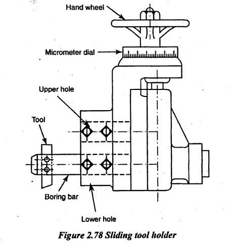
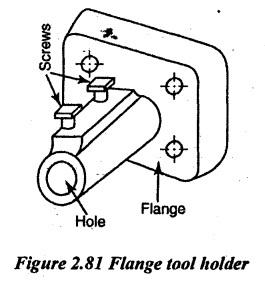
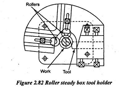
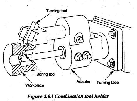
9. Tool Holding Devices

Manufacturing Technology: Unit II: Turning Machines : Tag: : Turning Machines - Manufacturing Technology - capstan and turret lathes
Related Topics
Related Subjects

Manufacturing Technology
ME3493 4th semester Mechanical Dept | 2021 Regulation | 4th Semester Mechanical Dept 2021 Regulation