Manufacturing Technology: Unit III: Reciprocating Machine Tools
Boring Machine
Reciprocating Machine Tools - Manufacturing Technology
Boring is the process of enlarging previously drilled holes with a single point cutting tool as shown in Figure 3.70.
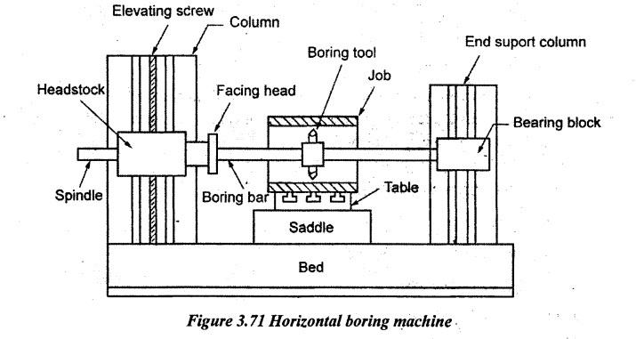
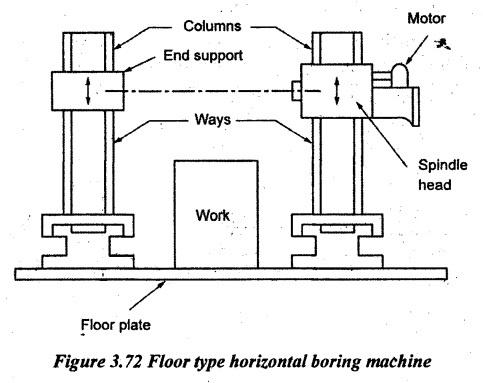
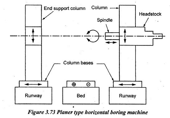
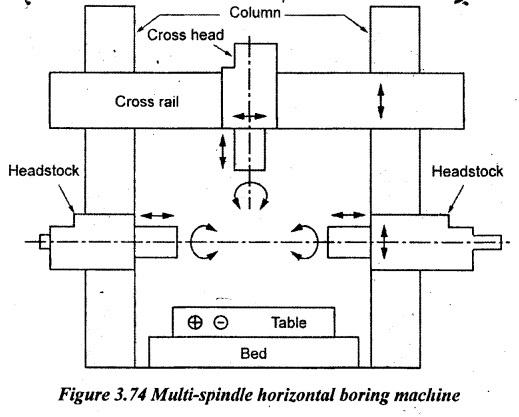
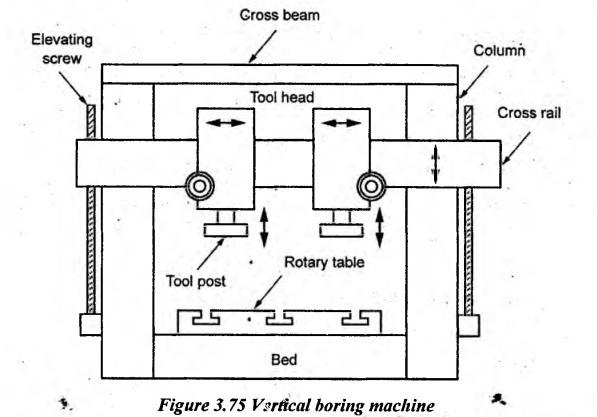
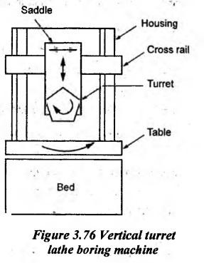
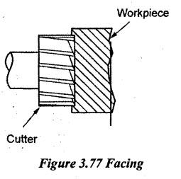
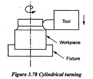
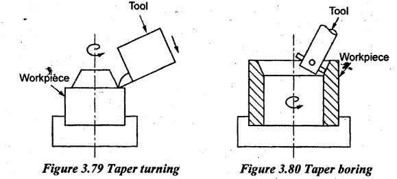
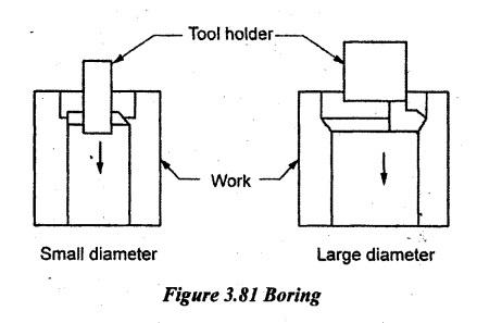
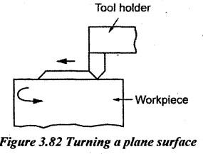
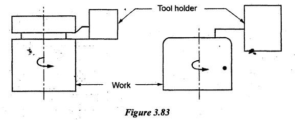
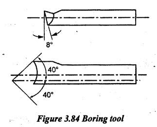
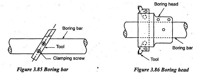
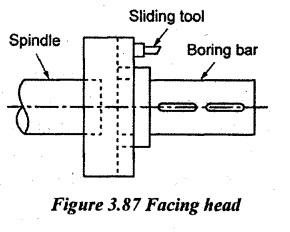
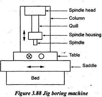
BORING MACHINE Boring is the process of enlarging previously drilled holes with a single point cutting tool as shown in Figure 3.70. The boring machine is one of the most versatile machine tools. Boring a small hole in a small workpiece can be done on a lathe. The boring machine is designed for machining large and heavy workpieces in mass production work such as boring engine frame, cylinder, machine housing etc. These machines can perform the following operations: (a) Drilling (b) Boring (c) Counterboring (d) Spot facing (e) Internal and external thread cutting (f) Face milling (g) Facing and turning cylindrical surfaces (h) Gear cutting etc. The workpiece where a hole already exists is mounted on the table. The single point cutting tool for broaching operation is mounted on a bar called “boring bar". The workpiece is rotated against the boring tool while boring. The boring machines may be classified as follows. 1. Horizontal boring machine a) Table type b) Floor type c) Planer type d) Multiple head type 2. Vertical boring machine 3. Precision boring machine 4. Jig boring machine. The horizontal boring machine is intended to perform operations on relatively large pieces which cannot easily be rotated and they require operations on many surfaces. It can be used to drill, bore and ream holes and to mill flat surfaces. In mass production, holes of larger diameter are bored in multiple-spindle boring machines using boring cutter heads as tools. A horizontal boring machine has two vertical columns. A headstock slides up and down in one column. It may be adjusted and clamped to any desired height. The headstock holds the cutting tool. The cutting tool revolves in the headstock on a horizontal axis. A sliding type bearing block is provided on the other vertical column. It is used to support the boring bar. The workpiece is mounted on the table and clamped with ordinary strap clamps, T-slot bolts and nuts or it is held in a special boring fixture if required. The tool is fed into the work for boring. The various types of horizontal boring machines are described below. 1. Table Type Horizontal Boring Machine It is the most familiar machine and consists of headstock, column; base, table, saddle, send support and bed. The block diagram of this type is shown in Figure 3.71. The bed is a box type heavy cast iron structure and it supports vertical column, supporting column and table. The table is mounted on a saddle which longitudinally moves on bed ways. The table also slides crosswise direction. The box type vertical column supports the headstock and moves up and down on the vertical guide ways provided on the front face of the column. The end support column can be positioned along the bed towards or away from the headstock. It carries a bearing for supporting the end of a boring bar. The headstock carries a spindle which can longitudinally be moved for feeding the tool. The feed can alternatively be done by travelling a table parallel to the spindle axis. This method of boring with a longitudinal feed of the table is employed when the holes are of considerable length and bending of the boring bar is possible. Both speed and feed mechanisms are provided in the headstock. Changing of speed and feed are done by changing the positions of levers. 2. Floor Type Horizontal Boring Machine Large and heavy workpieces are bored in a floor type horizontal boring machine. Figure 3.72 shows this type of boring machine. In this type, there is no table and the job is mounted on a stationary T-slotted floor plate. The headstock supporting column and end supporting columns are mounted on separate runways. The work is kept stationary and the spindle can be moved crosswise, up and down and longitudinal directions. Other mechanisms are similar to the previous one. 3. Planer Type Horizontal Boring Machine It consists of headstock, column, column base runway, end support, end support runway, table and bed. A block diagram of this type is shown in Figure 3.73. All principal parts are similar to the table type but the work supporting mechanism is different. The table reciprocates at a right angle to the spindle which is similar to a planer. The headstock Manufacturing Technology supporting column is rigidly fixed. The end-supporting column may be moved towards or away from the bed. This arrangement helps to accommodate the different width of work. 4. Multi-Spindle Horizontal Boring Machine It consists of two or four headstocks, two columns, bed, table and cross-rails. The two vertical columns are mounted on the base bridged by a cross rail. The long bed supports the table. The table reciprocates on it. The cross slides carry one or two vertical headstocks. Each vertical column carries one horizontal headstock. Hence, four tools can simultaneously be mounted on this machine. All headstocks may be swiveled for angular cuts. It is the only machine that can do vertical as well as horizontal boring operations. Main specifications of a horizontal boring machine are designated by the following. 1. Type of machine: floor type, planer type, or multi spindle etc. 2. Maximum size of boring spindle diameter in mm. 3. Maximum spindle travel in horizontal and vertical direction in mm. 4. Maximum travel of the table in longitudinal and crosswise directions in mm. 5. Range and number of spindle speeds in rpm. 6. Range and number of spindle feeds in mm/rev. 7. Floor-space required for the machine in m2. 8. Weight of machine in Tonnes. 9. H.P of the machine motors. In vertical boring machines, the work rotates on a horizontal table about a vertical axis and the cutting tool is fed downwards. The three types of vertical boring machines are given below. 1. Vertical boring mill 2. Vertical turret lathe boring machine 3. Vertical precision boring machine. 1. Vertical Boring Mill It has a bed and two vertical columns. A cross beam connects two columns. A cross rail can move up and down on the vertical column. This movement is obtained by elevating screws. There are two tool heads which can horizontally move along the cross rail. This movement is used to machine flat horizontal surfaces. The tool post can vertically be moved downwards to produce cylindrical surface. The tool can also move at an angle towards the table to produce a tapered surface. The machine table is a circular casting. It is mounted at the top of bed. It is rotated about a vertical axis driven by a motor. The top of the table has T- slots for clamping the work. Vertical boring machines are used for machining inside and outside diameters of pressure vessels and facing of large pieces such as turbine castings, flywheels, tables of machine tools, gear blanks, locomotive wheels etc. 2. Vertical Turret Lathe Boring Machine The workpiece is clamped on a table by adjustable jaws and it is identical to lathe Chuck which rotates about its vertical axis. It has an arrangement of a multiple tooling turret mounted on the cross rail. The cross rail can vertically be adjustable and the saddle holding the turret may be moved cross-wise by hand or power. The machine is not only suitable for boring but also for turning of gear blanks, piston rings, railroad wheel etc. During horizontal boring operations, generally, the workpiece remains stationary while. the cutter is rotated through the hole. Several operations such as drilling, boring, counter- boring, spot facing, reaming etc., can simultaneously be done on a job with high accuracy. The various operations are described below. (a) Boring: The boring procedure is described in Figure 3.76. Here, the work is stationary and the tool rotates. Holes are bored by using boring bars. The boring bar is fitted to the spindle. Boring bar has slots for inserting single point cutting tools. The tool is adjusted in the boring bar to the required dimension and clamped by setscrews. The depth of cut can be given by vertically moving the cross slide or by moving the table in the crosswise direction. (b) Facing or face milling: Facing cutter is similar to end milling cutter and it is used in a horizontal boring machine for machining flat surfaces on the workpiece as shown in Figure 3.77. The face mill is fitted to the boring machine spindle. The cutter rotates about the horizont axis of the spindle. The feed is given by moving the table in a cross-wise direction. The depth of cut is given by adjusting the saddle along the machine bed. (c) Drilling: For drilling, the drill is fitted to the headstock spindle. The workpiece is fed against the drill through the longitudinal movement of the saddle. (d) Reaming: In the case of reaming process, the reamer is fitted to the headstock spindle instead of the drill as in the previous case. Other procedures are similar to the drilling process. In a vertical boring, the job rotates and the tool is fed into it. A vertical boring machine may be used for the operations such as cylindrical turning, taper turning, boring, taper boring, necking, forming, machining horizontal flat surface, grooving or shoulder turning etc. For necking and forming, the cross feed is given. For external and internal taper turning operations, the tools head is swiveled to a required angle and the down feed is given. Some of the operations are explained below. (a) Cylindrical turning: For cylindrical turning operations, the tool head is locked to prevent the horizontal movement along the cross rail. Then the tool post in tool head is fed downwards to turn the surface. To give the depth of cut, the tool head is unlocked and moved along the cross rail. (b) Taper turning: Both internal taper and external taper can be produced in a vertical boring machine. The tool head is swiveled to the required angle and hence, the tool is fed at the required angle. The cross-feed of the tool head is locked during taper turning operation. (c) Boring: Boring small diameter is done by using a boring bar. The boring bar is attached to the tool head. The downward movement of the tool is given by a tool head. For boring the large diameter, the tool head is directly fed into the work. (d) Turning a plane surface: For turning a flat horizontal surface, the tool is given crosswise movement i.e. perpendicular to the axis of rotation of the workpiece. It is done by giving the cross feed of the tool head. The depth of cut is given by downward adjustment of a tool head. While turning, the tool head and cross rail are locked in position. (e) Necking, cutting off and forming: Necking or cutting off and forming operations are done by giving the cross feed to the tool head. In the cutting off operation, a cutting off tool or parting tool is used. In necking, a tool of required width is used. A forming tool is used in the forming operation. Boring tools are held in boring tool holders which may be either a fixed or rotating type. The boring bar or the boring head is connected to the main spindle of the machine. Boring tools may be a single point or multipoint tools. The typical single point cutting tool generally used in the boring machine is shown in Figure 3.84. (a) Boring bar: The single point cutting tool is held in a boring bar by means of setscrews. The boring bar is used for boring long bores. One end of the boring bar is held in the spindle whereas the other end is supported by a bearing on the end-supporting column. (b) Boring head: A simple type of boring head is shown in Figure 3.86. It has a circular body. It can be fastened at any désired place on a bar by means of keys or screws. Two or three square slots are radially made in the body. Tool bits are fitted in these slots and secured in position by means of setscrews. The boring head gives a maximum support to tools. If more tools are used, the operation will be faster. (c) Facing head: Facing heads are mounted at the end of the spindle for facing, external turning and enlarging holes. It has a flange having a diametrical slide way. The tool can be adjusted along the slide way. A jig boring machine is a precision boring machine used for boring accurate holes at proper center-to-center distances. It is a specially designed machine tool for the precision location and production of holes needed in jigs, fixtures, dies and templates. The machining accuracy of holes produced by this machine tool lies within the range of 0.0025mm.-The built-in precision measuring devices for axis movement is another specialty of this machine. This machine is also used for prototype production of accurate parts, production of parts in small quantities where the investment in tooling is not desirable, workpieces such as drill jigs and in general, the parts require very high accuracy. In appearance and construction, a jig boring machine resembles a vertical milling machine but it is more rigid and accurate. The spindle and other parts of this machine are very rigid to resist deflection. There are mainly two types of jig boring machines. (a) Single vertical column type (b) Planer type. (a) Single vertical column type jig boring machine: A block diagram of this type is shown in Figure 3.88. It is most extensively used type of a jig boring machine. It is used in precision tool room applications such as jigs, fixtures, templates, dies, castings and other components. It can also be used for carrying out light milling operations. It consists of the following parts. (i) Bed (ii) Column (iii) Spindle head (iv) Table (v) Saddle. The member that supports the machine is known as bed. It is a box-shaped casting made of cast iron. To provide more rigidity, it is provided with stiffened ribs. It supports the column, saddle and whole machine and also all electrical controls of the machine. The column is a hollow vertical cast iron structure which supports the spindle head, quill, spindle housing and guide ways. The spindle can slide up and down on vertical guide ways of the column. There is a quill attached to the spindle head. The spindle housing is fitted at the bottom of the quill. The spindle housing is made of a special metal called invar. The machine spindle rotates in an accurate antifriction bearing. A saddle moves on horizontal guide ways over the bed. The table is fitted over the saddle. The table can be adjusted crosswise direction. Generally, the table is provided with T- slots at the top surface for clamping the workpiece. The saddle permits the work longitudinally to move. Both longitudinal and transverse motions to the table and saddle are given by a separate electrical motor fitted inside the bed. The various machine operations are controlled by means of pick up drives. Vernier calipers are provided for setting the table by hand. They are mounted on the table as well as on the saddle. They are needed for making accurate measurements and automatic movements of mechanisms to preset dimensions. The machine is usually kept in an air-conditioned room to eliminate the effects of the atmosphere. (b) Planer type jig boring machine: The construction of this type resembles a planer and therefore, it is called planer type. It consists of two vertical columns supported at two sides of the bed. The columns support the cross-rails. The spindle head moves over cross rails. The table has a reciprocating movement. By moving the table and the spindle head, the position of job can be adjusted to any convenient position to carry out the boring operation. A planer type-boring machine is rigid in construction and it is used for boring operations on bigger components.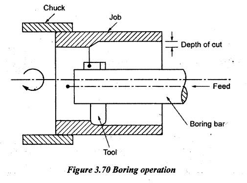
1. TYPES OF BORING MACHINE
2. HORIZONTAL BORING MACHINE
3. SPECIFICATIONS OF A HORIZONTAL BORING MACHINE
4. VERTICAL BORING MACHINE
5. HORIZONTAL BORING MACHINE OPERATIONS
6. VERTICAL BORING MACHINE OPERATIONS
7. BORING TOOLS
8. JIG BORING MACHINE
Manufacturing Technology: Unit III: Reciprocating Machine Tools : Tag: : Reciprocating Machine Tools - Manufacturing Technology - Boring Machine
Related Topics
Related Subjects

Manufacturing Technology
ME3493 4th semester Mechanical Dept | 2021 Regulation | 4th Semester Mechanical Dept 2021 Regulation