Theory of Machines: Unit III: Friction in Machine Elements
block or shoe brakes
Friction in Machine Elements - Theory of Machines
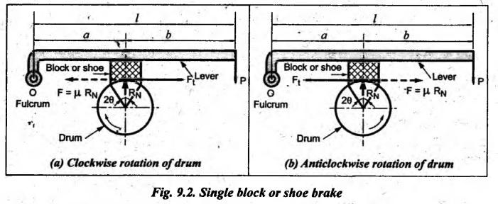
In this type of brake, one or more blocks or shoes are pressed against the rim surface of a brake drum.
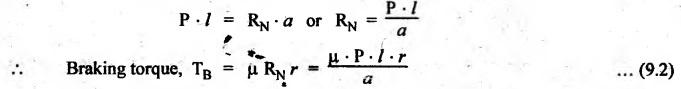
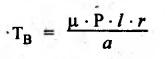
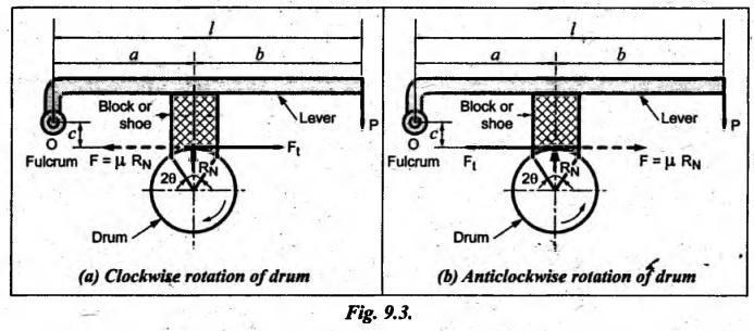
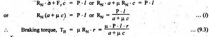
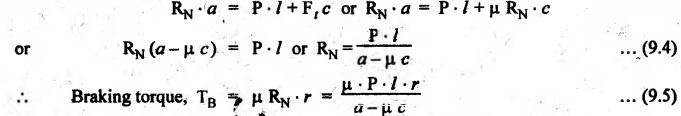
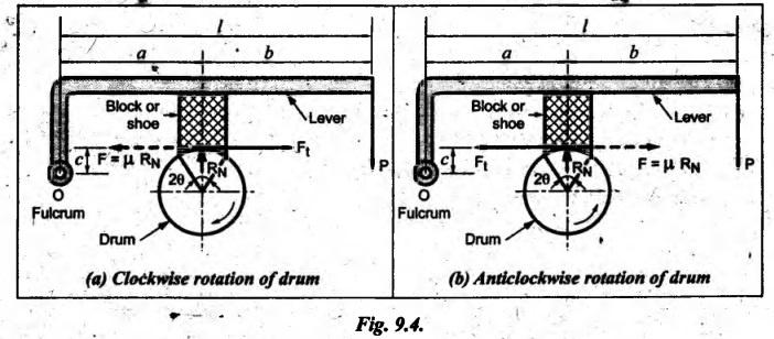
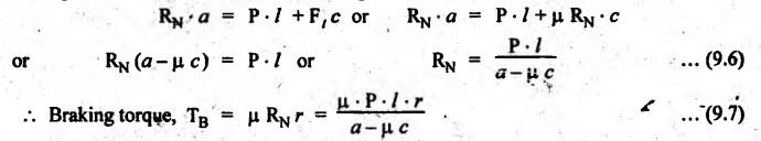
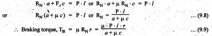
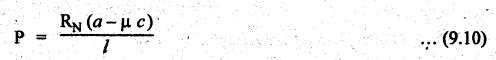
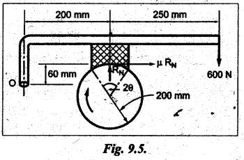
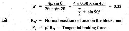
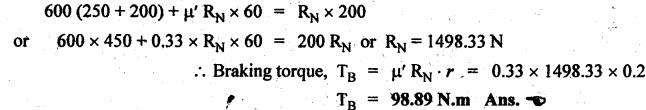
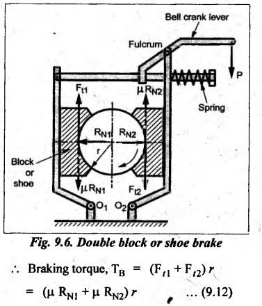
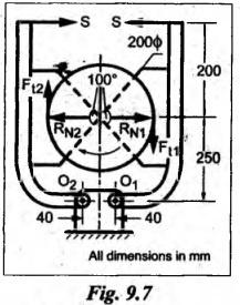
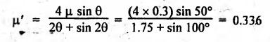
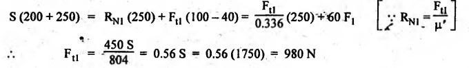
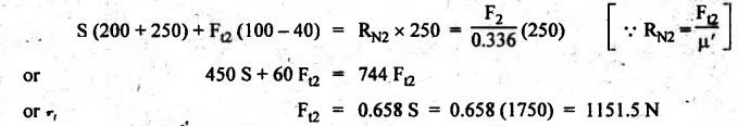
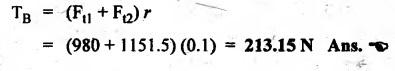
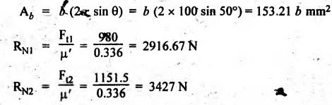
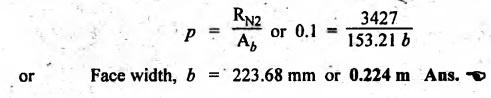
BLOCK or SHOE BRAKES In this type of brake, one or more blocks or shoes are pressed against the rim surface of a brake drum. The blocks are made of wood, asbestos in rubber compound, cast iron or of any other suitable metal. The material of the block or shoe is softer than that of the drum. The blocks are pressed against the rim by the application of a force through suitable leverage or brake hanger. A single block brake is shown in Fig.9.2. It consists of one block or shoe which is pressed against a rotating drum by means of the lever. This type of brake is commonly used in bicycles and locomotives. Let P = Force applied at the end of the lever, r = Radius of the drum, μ = Coefficient of friction, RN = Normal reaction of the block, F = μ RN = Frictional force acting on the block, Ft = Tangential braking force acting on the block (which is equal and opposite to frictional force F), 2θ = Angle of contact surface of the block, and TB = Braking torque. When the angle of contact of the block on the brake drum is small i.e., 2θ < 60° t normal pressure between the block and the drum can be assumed to be uniform. In such cases, tangential braking force acting on the drum is equal to frictional force. That is, Ft = F = μ RN Now let us consider the three different cases possible. Case I: Line of Action of Tangential Breaking Force (F) Passes through the Fulcrum of the Lever (i) When the rotation of the drum is clockwise: Fig.9.2(a) shows the clockwise rotation of the brake drum. Taking moments about the fulcrum O, we get (ii) When the rotation of the drum is anticlockwise; Fig.9.2(b) shows the anticlockwise notation of the brake drum. It may be noted that braking torque for both clockwise and anticlockwise notation of the drum is the same and is given by Case II: Line of Action of the Tangential Braking Force (F) Passes through Distance 'c' below the Fulcrum O (i) When the rotation of the drum is clockwise: Consider the clockwise rotation of brake drum as shown in Fig.9.3(a). Taking moments about the fulcrum O, we get (ii) When the rotation of the drum is anticlockwise: Consider the anticlockwise rotation of the brake drum as shown in Fig.9,3(b). Taking moments about the fulcrum, we get Case III: Line of action of tangential braking force (F) passes through a distance 'c' above the fulcrum (i) When the rotation of the drum is clockwise: Consider the clockwise rotation of the brake drum as shown in Fig.9.4(a). Taking moments about the fulcrum O, we get (ii) When the rotation of the drum is anticlockwise: Consider the anticlockwise rotation of the brake drum as shown in Fig.9.4(b). Taking moments about the fulcrum O, we get From equations (9.5) and (9.7), the expression for the force required to apply the brake is obtained as If a ≤ μc, then P will be negative or zero. This means that no external force is required to apply the brake and hence the brake is self-locking. ⸫ Condition for self-locking: a ≤ μc From equation (9.10), we can write In the above expression, it may be observed that the moment of the applied force (F. l) and the moment of the frictional force (μ RN • c) about O are in the same direction. Thus the frictional force helps in applying the brake. Such type of brake is known as self-energizing brake. Note 1. In actual practice, the brake should be self-energizing and not self-locking. Thus if P = 0, it is a self-locking brake and if P > 0, then it is a self-energizing brake. 2. Pivoted block or shoe brake (2θ > 60°): So far (when 2θ > 60°) it is assumed that the normal reaction (RN) and the frictional force (μ RN) acts at the mid point of the block. But when the angle of contact is more than 60° i.e., 2 θ > 60°, then the normal pressure is lesser at the sides than at the centre. In such cases, μ has to be replaced by an equivalent coefficient of friction μ'. where μ = Actual coefficient of friction, and 2θ = Angle of contact Example 9.1 A single block brake is shown in Fig.9.5. The diameter of the drum is 400 mm and the angle of contact is 90°. If the operating force of 600 N is applied at the end of a lever and the coefficient of friction o between the drum and the lining is 0.30, determine the torque that may be transmitted by the block brake. Given data: d = 400 mm or r = 200 mm = 0.2 m; Solution: Since the angle of contact is greater than 60°, therefore equivalent coefficient of friction, Taking moments about the fulcrum O, we get Example 9.2 A bicycle and rider of mass 100 kg are travelling at the rate of 16 km/hr on the level road. A brake is applied to the rear wheel which is 0.90 m in diameter and this is the only resistance acting. How far will the bicycle travel and how many turns will its wheel make before it comes to rest. The pressure applied on the brake is 100 N and μ = 0.05. Given data: m = 100 kg; v = 16 km/hr = 4.444 m/s; D= 0.9 m; RN = 100 N; μ = 0.05. Solution: Distance travelled by the bicycle before it comes to rest: When the bicycle comes to rest, the work done against friction is equal to the kinetic energy of the bicycle. The kinetic energy of the bicycle is given by Let x = Distance travelled by the bicycle before coming to rest Equating equations (i) and (ii), we get Number of revolutions made by the bicycle before it comes to rest: Let N = Required number of revolutions We know that distance travelled by the bicycle (x), When only one block brake is used for braking, then there will be a side thrust on the bearing of wheel shaft. This produces the bending of the shaft. This drawback of the single block shoe can be removed by providing two blocks on the two sides of the drum as shown in Fig.9.6. This also doubles the braking torque. The blocks or shoes are held on the drum by means of spring force (through the force P applied on the bell-crank lever). The value of RNI is obtained by taking moments of the forces RNI, μ RNI and P about fulcrum O1. Similarly the value of RN2 is obtained by taking of the forces RN2, μ RN2 and P about fulcrum O2. Example 9.3 The brake whose dimensions are shown in Fig.9.7 has coefficient of friction of 0.3 and is to have a maximum pressure of 100 kPa against the friction material. (1) Using an actuating force of 1750 N, determine the face width of the shoes (both shoes have same width), and (2) What torque will the brake absorb? Given data: μ = 0.3; p = 1000 kPa = 1 × 10⁵N/m2; d = 200 mm or r = 100 mm = 0.1 m; 2θ = 100° = 100 × π/180° = 1.75 rad; S = 1750 N. Solution: Since 2θ > 40°, therefore equivalent coefficient of friction (i) Torque capacity: Consider the right hand side brake shoe: Taking moment about O1, we get Consider the left hand side brake shoe: Taking moment about O2, we get ⸫ Torque that the brake will absorb or torque capacity of the brake, (ii) Width of the brake shoes (b): We know that projected bearing area for one shoe, Since the maximum normal force is on the left hand side of the shoe, therefore we have to find width of the shoe for maximum normal force. i.e., RN2.1. Single Block or Shoe Brake

1. Self-Locking Brake
2. Self-Energizing (or Self-Actuating) Brake


2. Double Block or Shoe Brake
Theory of Machines: Unit III: Friction in Machine Elements : Tag: : Friction in Machine Elements - Theory of Machines - block or shoe brakes
Related Topics
Related Subjects

Theory of Machines
ME3491 4th semester Mechanical Dept | 2021 Regulation | 4th Semester Mechanical Dept 2021 Regulation