Manufacturing Processes: Unit IV: Sheet Metal Processes
Bending Process
Sheet Metal Processes
Bending is a manufacturing process that produces a V-shape, U-shape or channel shape along a straight axis in ductile materials, most commonly in sheet metal.
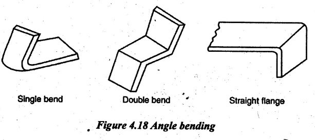
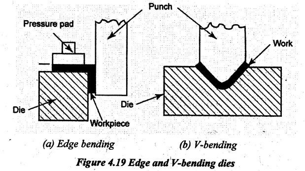
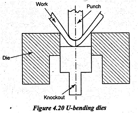
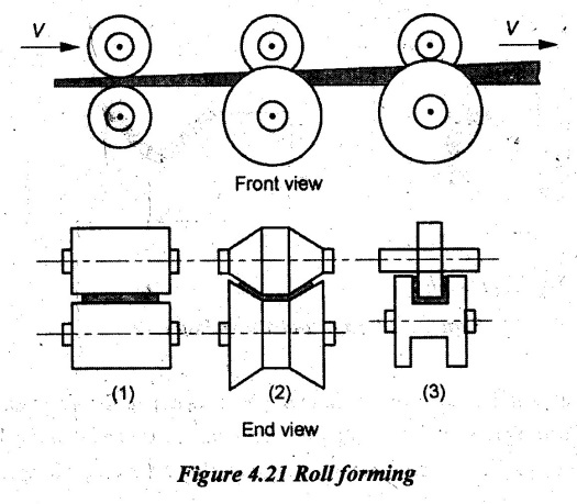
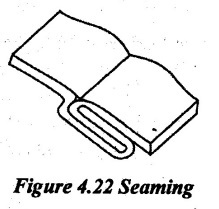
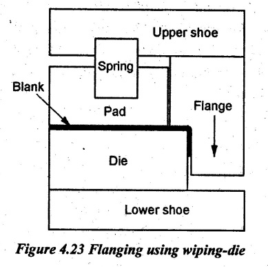
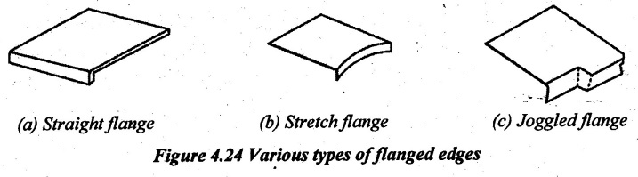
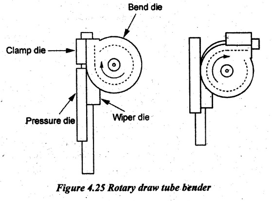
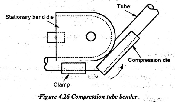
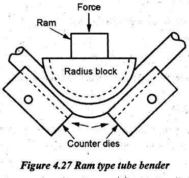
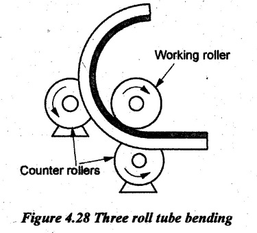
BENDING PROCESS Bending is a manufacturing process that produces a V-shape, U-shape or channel shape along a straight axis in ductile materials, most commonly in sheet metal. The workpiece is stressed beyond its elastic limit to obtain the required shape of bending. During bending, the metal flow is uniform which means that the cross-section of workpiece will remain the same. The portion below the neutral axis is subjected to compression and the portion above the neutral axis is subjected to tension. Hence, bending has to overcome both tensile stresses and compressive stresses. The axis which separates the portions of tension and compression is known as "Neutral axis" or "Neutral layer”. Generally, the bending is done perpendicular to the direction of grains in the workpiece. Bend angle is the angle between two extreme positions of bend radius. The corresponding area included between bend angles is known as bend area. The amount of bending is limited for different materials by the following factors: 1. Properties of material 2. Length of bend 3. Condition of the cut edge at the ends of bend line 4. Direction of orientation of the axis of the bend to the direction in which the material was rolled. The following points are to be considered during bending: (i) Material to be bent should be ductile and strong. It should not be hard. (ii) Bending is smooth if the axis of the bend is perpendicular to the direction of grains. (iii) Springback phenomenon should be taken care of. (iv) Holes pierced before bending will be distorted if they are close to the bend area. (v) In most of bending operations, the lubrication required is very less. Different bending operations are described below. (a) Angle bending: In angle bending, the metal is bent at an angle to each edge. The angle is denoted by 'θ'. If θ < 90° on side, it is called single bending. If θ = 90°, it is called vertical or straight bending or flanging. If θ < 90° but in two places on the same work, it is called double bending. (b) Edge bending: In edge bending, the material is bent at one edge with the help of a punch as shown in Figure 4.19 (a). (c) V-bending: V-bending is also called air bending. In this type of bending, the sheet metal is pressed by a V-shaped punch against V-shaped die. It forces the sheet metal into a bottom V-die which is mounted on the press. Figure 4.19 (b) illustrates the V-bending of sheet metals. The punch forms the bend so that the distance between punch and side wall of the V is greater than the material thickness (t). (d) U-bending: U-bending uses a U-shaped punch to form the required shape to the metal with the help of dies. Figure 4.20 illustrates the U-bending of sheet metals. (e) Roll forming: Roll forming is used for bending continuous length of the sheet metal and large production runs. The metal strip is bent in stages by passing it through a series of rolls as shown in Figure 4.21. (f) Seaming: The process of providing lock between two edges of the different work metals is called seaming. To perform this, the edges of sheet metal to be locked are bent in opposite direction to each other as shown in Figure 4.22. Then, they are inserted with each other and pressed or tightened to make the complete lock. (g) Flanging or edge bending or wiping-die bending: Flanging is a process of bending the edges of sheet metals to 90°. It is also called edge bending or wiping-die bending. Flanging is performed by holding the sheet between pad and die, sliding the wiping flange across the face pushing and bending the sheet metal which protrudes from the pad and die. The flange is driven by an upper shoe and the die is supported by a lower shoe as shown in Figure 4.23. A spring between pad and upper shoe grabs the metal before the flange hits it and holds the workpiece down during bending process. If the flange has a feature associated with it other than just a straight bend, a stronger spring will help to prevent the metal from being pulled from the area between die and pad. It will lead to less deformation when the piece comes out of the stamp. Various types of flanging are shown in Figure 4.24. (h) Tube bending: Bending and forming tubes, and other hollow sections require special tooling to avoid buckling and folding at bent corners. The oldest method of bending a tube or pipe is packing the tube with loose particles and bending the part using a suitable fixture. The commonly used packing material is sand. This techniques prevents the tube from buckling. After the tube has been bent, the sand is shaken out. Tubes can also be plugged with various flexible internal mandrels. Tube bending and fabrication equipment are used to bend tubes and pipes to a desired radius. There are several different types of tube and pipe bending machines as described below: Rotary draw (or mandrel) benders havę several tooling components as shown in Figure 4.25. A mandrel controls the flow of the material at the point of bend in order to maintain the shape of the tube as it sets into the arc of the bend. Pressure die holds the tube against the bend die under pressure. Clamp die clamps the tubing material to the bend die as it rotates to form the bend. Bend die (also referred as former die) is the form against which the tube is clamped and then drawn around to produce a bend. The radius of the bend die determines the form of the bend. Wiper die (also known as a wiper) prevents the formation of a wrinkle on the inside radius of the bend. Compression benders operate similarly to rotary draw benders. However, the bend die remains stationary in a compression bender as shown in Figure 4.26. Ram benders use a ram with a radius block that presses the tube or pipe against two counter rollers or wind dies as shown in Figure 4.27. The radius on the radius block tooling determines the form of the bend. Three roll benders have three rollers arranged in a pyramid shape as shown in Figure 4.28. It is used for larger bending radii. Roll benders are similar to ram bending but they use a working cylinder and two stationary counter rollers. The positioning of the three rolls determines the form of the bend. The tendency of the metal tries to resume its original position causing a decrease in bend angle known as springback. The springback varies from 0.5° to 5o for steel. Springback depends on the following factors. 1. Material type 2.- Thickness 3. Hardness 4. Bend radius. A greater springback is caused by large bend radius. To avoid larg bend radius, the following methods are used. 1. Over bending using V- die or air bends 2. Coining the metal slightly at corners to relieve elastic stresses.1. Bending Operations
2. Springback in Bending
Manufacturing Processes: Unit IV: Sheet Metal Processes : Tag: : Sheet Metal Processes - Bending Process
Related Topics
Related Subjects
Manufacturing Processes
ME3393 3rd semester Mechanical Dept | 2021 Regulation | 3rd Semester Mechanical Dept 2021 Regulation