Theory of Machines: Unit III: Friction in Machine Elements
belt tensions
Friction in Machine Elements - Theory of Machines
The belt drives primarily operate on the friction principle. That is, the friction between the belt and the pulley is responsible for transmitting power from one pulley to the other.
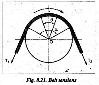
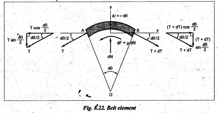
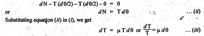
BELT TENSIONS • The belt drives primarily operate on the friction principle. That is, the friction between the belt and the pulley is responsible for transmitting power from one pulley to the other. • Due to the presence of friction between the belt and the pulley surfaces, tensions on both sides of the belt are not equal. The tension on the tight side (T1) will be higher than the tension on the slack side (T2). • Consider a belt drive, as shown in Fig.8.20. In Fig.8.20, driver pulley pulls the belt from one side (lower side CD) and delivers it to other side (upper side AB). So tension in the pulled side (i.e., side CD) will be more than the other side (i.e., side AB). Because of more tension on side CD, the side CD is known as tight side whereas the side AB (because of lesser tension) is known as slack side. • It may be noted that in case of horizontal belt drive system, the slack side of the belt is on the upper side and the tight side of the belt is always on the lower side. ■ Reason: Because, the slack side of the belt will sag due to its self-weight. Thereby the angle of contact between the belt and the pulleys will increase. However the tight side will not sag to that extent. Hence, the net effect will be an increase in the angle of contact. Thus, due to the increase in angle of contact, the power transmission capacity of the belt drive will increase. (Relationship Between Belt Tensions) The flat belt rolls over a pulley as shown in Fig.8.21. Since the belt must overcome the resistance of friction at the surface of contact, T1 must be greater than T2 in any case. Let T1 = Tension on the tight side of the belt in newtons, T2 = Tension on the slack side of the belt in newtons, θ = Angle of contact between pulley surface and belt in rad, and μ = Coefficient of friction between the belt and the pulley. Consider an infinitesimal element of belt which is in contact with the pulley. The FBD of the element, indicating all the forces acting on it, is shown in Fig.8.22. The belt portion AB is in equilibrium under the following forces: 1. Tension T in belt at A, 2. Tension T + dT in belt at B, 3. Normal force, dN, and 4: Friction force, dF = μdN. Applying the equation of force equilibrium along x-direction, we get Applying the equation of force equilibrium along y-direction, we get Since dθ is very small, sin (dθ/2) ≈ (dθ/2) and dT sin (dθ/2) ≈ 0. Substituting these, we Integrating this equation between the tension limits (i.e., T = T2 at θ = 0°, and T = T1 at θ = 0), we get Thus the above equation is known as limiting tension ratio of flat belt drive. Thus, the tension ratio is dependent on the coefficient of friction and angle of contact. It is independent of the diameter of the pulley. Note 1. The value of 0 in the tension ratio equation is the angle of lap in radians on smaller pulley of the belt drive. 2. The tension ratio must be calculated for the pulley (smaller or larger) which has least eμα value. Therefore while designing a belt drive, first one should find which of the pulley (smaller or larger) governs the design. 3. To find the governing pulley: (1) In the pen belt drive, the smaller pulley has the smaller angle of lap than that of the larger pulley and hence the slip will occur first on the smaller pulley. Therefore the limiting tension ratio must be calculated for smaller of the two pulleys. (ii) In the crossed belt drive, the angle of lap on both the smaller and larger pulleys are equal. Therefore the limiting tension ratio can be calculated for any of the two pulleys.
1. Limiting Tension Ratio for Flat Belt Drive


Theory of Machines: Unit III: Friction in Machine Elements : Tag: : Friction in Machine Elements - Theory of Machines - belt tensions
Related Topics
Related Subjects

Theory of Machines
ME3491 4th semester Mechanical Dept | 2021 Regulation | 4th Semester Mechanical Dept 2021 Regulation