Hydraulics and Pneumatics: Unit IV: Pneumatic and Electro Pneumatic Systems
Basic fluidic devices
Pneumatic and Electro Pneumatic Systems - Hydraulics and Pneumatics
Now we shall discuss the operation of the above fluidic devices in the following sections.
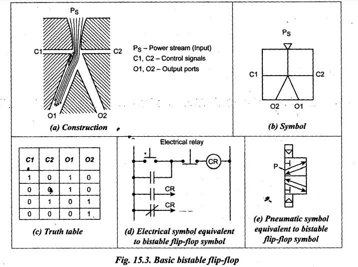
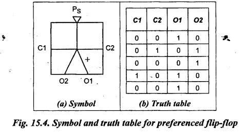
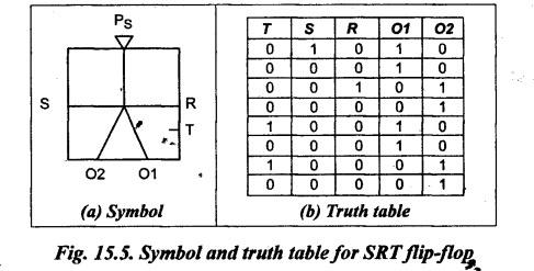
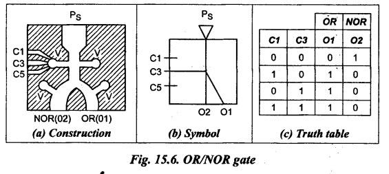
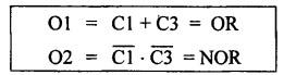
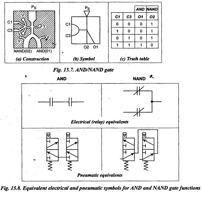
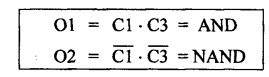
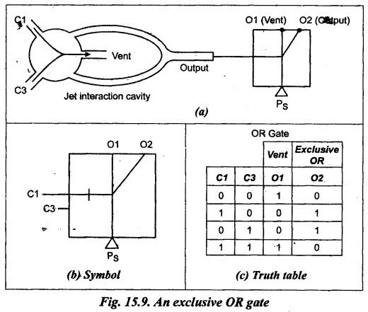
BASIC FLUIDIC DEVICES Some important basic fluidic devices are : 1. Basic bistable flip-flop, 2. Flip-flop with start-up preference, 3. SRT flip-flop, 4. OR/NOR gate, 5. AND/NAND gate, and 6. Exclusive OR gate. Now we shall discuss the operation of the above fluidic devices in the following sections. A basic bistable flip-flop provides controlled assurance as to which of the two output ports will deliver the power stream. 1. Construction A basic bistable flip-flop is illustrated in Fig.15.3(a). Figs.15.3(b) and (c) show the symbol and truth table of the basic bistable flip-flop respectively. Figs.15.3(d) and (e) show the equivalent electrical and pneumatic symbols for the bistable flip-flop function respectively. 2. Operation In this device, the air flow will be from input power stream (P) to either the Ol output port or the O2 output port, depending on the existence of a signal from either C1 channel or C2 channel. This device operates on the principle of the low pressure vortex being created on one side or the other of the element, creating the wall-attachment effect toward either the O1 or O2 output ports. The bistable flip-flop derives its name from the fact that it has two stable conditions, O1 and O2, and it can be made to switch or flip from one to the other. 3. Use The bistable flip-flop device is normally used as a memory device. This can be understood from the symbol and-truth table of the bistable flip-flop, as shown in Figs. 15.3(b) and (c). 4. Truth Table A truth table helps to describe the functioning of that particular device. In truth table, the number O refers OFF and the number 1 refers ON for all devices. From the truth table of . bistable flip-flop (Fig.15.3(c)), one can interpret the following points : • For the first row: "When control signal C1 is ON and control signal C2 is OFF, then the output is at 01 (and there is no output at O2). • For the second row: If both control signals C1 and C2 are turned OFF, then the output is at O1. • For the third row: When C1 is turned OFF and C2 is ON, then the output is at O2. • For the fourth row: Now, removing the signal C2 leaves the device at the second stable state with the output of O2. Thus the flip-flop has two stable states when all control signals are OFF. Also when both control signals C1 and C2 are turned ON simultaneously, the supply pressure splits and there is no useful output to such condition. Thus when both C1 and C2 are ON, the flip-flop does not produce useful digital ON/OFF output signals. A flip-flop with start-up preference is used in applications where a specific output is required when the power supply is first turned ON and all controls are OFF. 1. Construction The construction and operation of the flip-flop with start-up preference is very much similar to that the basic flip-flop. The symbol and truth table of the flip-flop with start-up preference are shown in Figs. 15.4(a) and (b) respectively. 2. Operation In Fig.15.4(a), the plus (+) sign indicates that the output Ol is preferred over O2. This can be accomplished by building the splitter slightly off center. That's why when the flip-flop first receives its power supply (and control signals are OFF), the wall attachment is preferenced to the O1 output. 3. Truth Table The only difference of the truth table (Fig.15.4(b)) of preferenced flip-flop over the truth table (Fig.15.3(c)) of basic flip-flop is that when all control signals are OFF, the output is ON at O1 and OFF at 02 (as shown in the first row of the Fig.15.4(b)). All the remaining functions are exactly the same as that of basic flip-flop (which can be seen from the last four rows of both Figs.15.4(b) and 15.3(c)). In addition to all the capabilities of a basic flip-flop, a SRT flip-flop can also switch by applying a signal to the trigger port. The name SRT flip-flop is an acronym for SET-RESET- TRIGGER flip-flop. 1. Construction The symbol and truth table for a SRT flip-flop are shown in Figs.15.5(a) and (b) respectively. In Fig. 15.5(a), the letters 'S' and 'R' stand for SET and RESET respectively. They perform as regular control signals similar to C1 and C2 in basic flip-flops. The letter 'T' stands for TRIGGER, whenever trigger signal is applied, it switches the output. 2. Operation The readers can read and understand the symbol and truth table of the SRT flip-flop in the same manner as discussed earlier. In Fig.15.5(b), the first column shows the status of the trigger control signal. Whenever this trigger (T) signal is turned ON, it switches (compliments) the output. 1. What do you mean by a Monostable Device ? • Further developments of the basic flip-flops led to the monostable device with more than one control input. • A monostable device is required to perform monostable function which is analogous to spring return function. In this device, when the control signal is removed, the device will switch back to the favoured output. • The basic flip-flop, preferenced flip-flop and SRT flip-flop discussed so far-are all bistable devices. They perform basically memory functions. • The two important monostable fluidic devices are : 1. OR/NOR gate, and 2. AND/NAND gate. 2. Construction of OR/NOR Gate The construction and operation of an OR/NOR gate is illustrated in Fig.15.6(a). Figs. 15.6(b) and (c) show its symbol and truth table respectively. In this, the 01 port represents the OR output and the O2 port represents the NOR output. 3. Operation The OR/NOR gate has two outputs corresponding with two conditions: (i) OR(01)—pressure at one or any combination of the control ports; and (ii) NOR(02)—pressure at none of the control ports. A control signal at any one or any combination of these ports will switch the device to the O1 output. With all control signals OFF, the device will be automatically switched to O2 output. Normally the OR/NOR gate is designed in such a manner that flow will always be in the NOR leg when no control signal is present. Also OR/NOR gate is available with multiple input signals, as shown in Fig.15.6(b). 4. Notations Representing Operations The desired practice, while describing fluidic components or designing circuits, is to use standard logic notation. Some of the standard logic notations are given below : (i) A • (dot means AND). (ii) +(plus sign) means OR. (iii) Bar over a letter (Ā) means that the condition represented by the "A" is absent. This notation is read as 'NOT A’. Using the above notations, the operation of the OR/NOR gate can be written as follows : It should be noted that NOR means NOT OR. ⸫ NOR = NOT OR = 5. Uses The OR/NOR gate is the basic logic building block. The OR/NOR block can be used in various ways to achieve all of the other logic functions. 1. Construction The construction and operation of an AND/NAND gate is illustrated in Fig.15.7(a). Figs. 15.7(b) and (c) show its symbol and truth table respectively. Fig.15.8 gives the equivalent electrical and pneumatic symbols for the AND/NAND gate functions. 2. Operation The operation of AND gate is similar to the NOR gate, except that the NOR gate is used to determine when none of the controls is present [see first row in Fig.15.6(c)], whereas the AND gate is used to determine when all the control signals are present [see the last row in Fig.15.7(c)]. In Fig.15.7(b), both the C1 and C3 control signals must be present to get an output at the 01 port (AND function). The absence of either or both will result in the stable output at the O2 port (NAND function). Using the logic notations, the operations of the AND/NAND gate can be written as follows: It should be noted that NAND means NOT AND. ⸫ NAND = NOT AND = An exclusive OR gate is a device that provides an output only when C1 or C3 or C5 or C7 (but not any combination of control signals) is ON. 1. Construction The construction and operation of an exclusive OR gate is illustrated in Fig.15.9(a). Figs. 15.9(b) and (c) show its symbol and truth table. 2. Operation The exclusive OR gate is obtained by feeding the output of a jet interaction cavity into the control port of an OR gate, as shown in Fig.15.9(a). When control signal C1 or C3 is ON, the jet interaction cavity produces an output at 02 port. This can be seen in the 2nd and 3rd rows of the truth table (Fig.15.9(c)). When both C1 and C3 control signals are ON, then their interaction causes them to vent to the atmosphere and hence there is no output at port 02. This can be seen in the 4th row of the truth table [Fig.15.9(c)]. Note • The truth tables are formed based on the concept known as 'Boolean Algebra'. • Boolean algebra is an ‘algebra of logic". This system formulated logical statements symbolically so that they could be written and proven in a similar manner as used in ordinary algebra. This is the algebra of proportions where only two possibilities-true or false--are allowed. In Boolean algebra, only two numbers---0 and 1-are used. • Functions: Boolean algebra provides the following two functions relative to fluid power systems : 1. It provides a means by which a logic circuit can be reduced to its simplest form. 2. It allows for the quick synthesis of a circuit that is to perform desired logic operations.1. Basic Bistable Flip-Flop
2. Flip-Flop with Start-up Preference
3. SRT Flip-Flop
4. OR/NOR Gate
![]()
5. AND/NAND Gate

6. Exclusive OR Gate
Hydraulics and Pneumatics: Unit IV: Pneumatic and Electro Pneumatic Systems : Tag: : Pneumatic and Electro Pneumatic Systems - Hydraulics and Pneumatics - Basic fluidic devices
Related Topics
Related Subjects

Hydraulics and Pneumatics
ME3492 4th semester Mechanical Dept | 2021 Regulation | 4th Semester Mechanical Dept 2021 Regulation