Theory of Machines: Unit III: Friction in Machine Elements
band brake
Friction in Machine Elements - Theory of Machines
In band brake system, a flexible band or belt is partially wrapped around a brake drum.
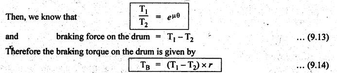
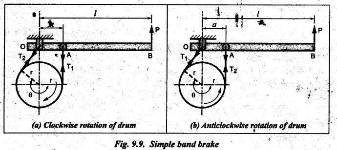
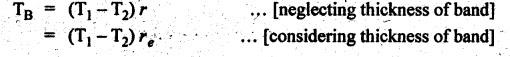
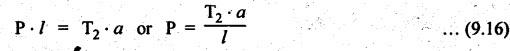
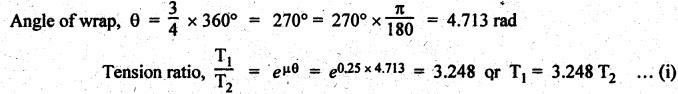
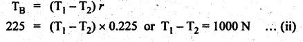
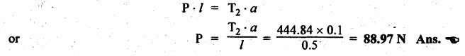
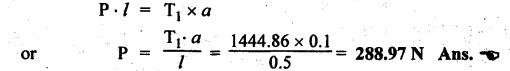
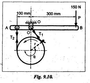
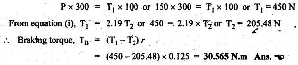
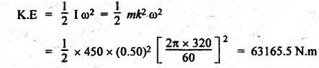
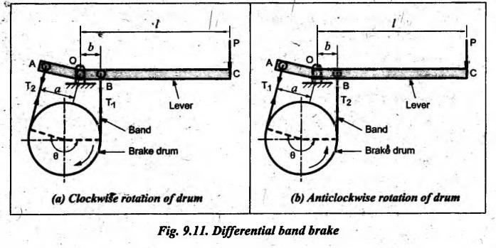
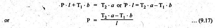
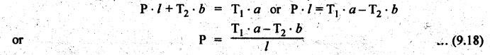
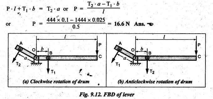
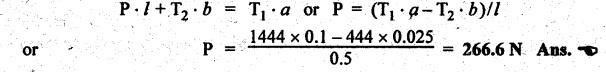
BAND BRAKE In band brake system, a flexible band or belt is partially wrapped around a brake drum. A force is applied at one end of the band through lever mechanism. The drum rotates and the band remains stationary. When the force is applied at the free end of the lever, the band is pressed against the surface of the drum. Thus the friction retards or stops the motion. Refer Fig.9.8. Let T1 = Tension in the band on tight side, T2 =Tension in the band on slack side, μ = Coefficient of friction between the band and the drum, θ = Angle of lap, and r = Radius of the drum. Types of band brakes: Two types of band brakes are 1. Simple band brakes, and 2. Differential band brake Fig.9.9 shows a simple band brake. The band or rope is wrapped round the cylindrical drum. When a force P is applied to the lever at B, the lever turns about the fulcrum pin O and tightens the band on the drum and hence the brakes are applied. The friction between the band and the drum provides the braking force. Let P = Force applied on the lever, r = Radius of the drum, t = Thickness of the band, re = Effective radius of the band = r + (t/2), θ = Angle of lap of the band on the drum, and T1 and T2 = Tension in the tight and slack sides of the band respectively. We know that braking torque on the drum, (i) Value of P when the rotation of the drum is clockwise: For the clockwise rotation of drum as shown in Fig.9.9(a), the end of the band connected to the fulcrum O will be slack side with tension T2 and the end of the band attached to A will be tight side with tension T1. Taking moment about the fulcrum O, we get (ii) Value of P when the rotation of the drum is anticlockwise: For the anticlockwise rotation of drum as shown in Fig.9.9(b), the end of the band connected to the fulcrum O will be tight side with tension T1 and the end of the band attached to A will be slack side with tension T2. Taking moments about the fulcrum O, we get Note 1. It may be noted that for a simple hand brake, one end of band is always connected to the fulcrum. 2. If the permissible tensile stress (σ) for the material of the band is given, then maximum tension in the band is given by, Τ1 = σ • w • t where w = Width of the band, and t = Thickness of the band. Example 9.4 A band brake acts on the 3/4 of circumference of a drum of 450 mm diameter which is keyed to the shaft. The band brake provides a braking torque of 225 N.m. One end of the band is attached to a fulcrum pin of the lever and the other end to a pin 100 mm from the fulcrum. If the operating force is applied at 500 mm from the fulcrum and coefficient of friction is 0.25. Find the operating force when the drum rotates in the (4) anticlockwise direction, and (ii) clockwise direction. Given data: d = 450 mm or r = 225 mm = 0.225 m; TB = 225 N.m; a = OA = 100 mm = 0.1 m; l = OB = 500 mm = 0.5 m; μ = 0.25 Solution: Let P = Operation force (i) Operating force when drum rotates in anticlockwise direction: Refer Fig.9.9(b) in which the drum is rotating in anticlockwise direction. We know that braking torque (TB), Solving equations (i) and (ii), we get T2 = 444.84 N and T1 = 1444.84 N Taking moments about fulcrum O (refer Fig.9.9(b)), we get (ii) Operating force when drum rotates in clockwise direction: Refer Fig.9.9(a) in which the drum is rotating in clockwise direction. When the drum rotates in clockwise direction, the tensions T1 and T2 will interchange their positions. Taking moments about the fulcrum O (refer Fig.9.9(a)), we get Example 9.5 A simple band brake shown in Fig.9.10, is applied to a shaft carrying a flywheel of mass 450 kg and of radius of gyration 500 mm. The shaft speed is 320 rpm. The drum diameter is 250 mm and the coefficient of friction is 0.2. The angle of lap of the band on the drum is 225°. Determine: (i) the brake torque when a force of 150 N is applied at the lever end, (ii) the number of turns of the flywheel before it comes to rest, and (iii) the time taken by the flywheel to come to rest. Given data: m = 450 kg; k = 500 mm 0.5 m; N = 320 rpm; μ = 0.2; θ = 225° = 225° × π/180° = 3.927 rad; P = 150 N. Solution: (i) Brake torque applied at the lever end: Taking moments about the fulcrum O, we get (ii) Number of turns of flywheel before it comes to rest (n): We know that kinetic energy of flywheel is given by This kinetic energy is used to overcome the work done due to the braking torque (TB). (iii) Time taken by the flywheel to come to rest: In a differential band brake, as shown in Fig.9.11, the ends of the band are joined to the lever AOB at points A and D. Point O is the fulcrum. It may be noted that for the band to tighten, the length OA must be greater than the length OB. Thus in the differential band brake no end of the band is connected to the fulcrum. (i) When the rotation of the drum is clockwise: Fig.9.11(a) shows the clockwise rotation of the brake drum. When the drum rotates in clockwise direction, the end of the band attached at B will be tight with tension T1 and end of band attached at A will be slack side with tension T2. Taking moments about the fulcrum O, we get (ii) When the rotation of the drum is anticlockwise: Fig.9.11(b) shows the anticlockwise rotation of the brake drum. When the drum rotates in anticlockwise direction, the end of the band attached at A will be tight side with tension T1 and end of band attached at B will be slack side with tension T2. Taking moments about the fulcrum O, we get Note 1. In equations (9.17) and (9.18), if the force P is zero or negative, then the brake becomes self-locking. The conditions for self-locking are: 2. In Figs.9.11(a) and (b), when length OA > OB, then the force P must act vertically in downward direction in order to apply the brake. Similarly, when the length OB > OA, the force P must act vertically in upward direction in order to apply the brake. Example 9.6 A differential band brake acting on the 3/4th of the circumference of a drum of 450 mm diameter, is to provide a braking torque of 225 N.m. One end of the band is attached to a pin 100 mm from the fulcrum of the lever and the other end to another pin 25 mm from the fulcrum on the other side of it where the operating force is also acting. If the operating force is acting at 500 mm from the fulcrum and the coefficient of friction is 0.25, find the two values of the operating force corresponding to two directions of rotation of the drum. Given data: d = 450 mm or r = 225 mm = 0.225 m; TB = 225 N.m; a = 100 mm = 0.1 m; b = 25 mm = 0.025 m; l = 500 mm = 0.5 m; μ = 0.25 Solution: We know that angle of wrap, Let P = Operating force applied at the end of the lever We know that the tension ratio, We also know that the braking torque, On solving equations (i) and (ii), we get T1 = 1444 N, and T2 = 444 N Operating force (P) for the clockwise rotation of the drum: When the drum rotates in clockwise direction, the end of band attached at B will be tight with tension T1 and end of band attached at A will be slack side with tension T2, as shown in Fig.9.12(a). Taking moments about the fulcrum O (Fig.9.12(a)), we get Operating force (P) for the anticlockwise rotation of the drum: When the drum rotates in anticlockwise direction, the end of the band attached at A will be tight side with tension T1 and end of band attached at B will be slack side with tension T2, as shown in Fig.9.12(b). Taking moments about the fulcrum O, we get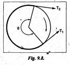
1. Simple Band Brakes


2. Differential Band Brake


Theory of Machines: Unit III: Friction in Machine Elements : Tag: : Friction in Machine Elements - Theory of Machines - band brake
Related Topics
Related Subjects

Theory of Machines
ME3491 4th semester Mechanical Dept | 2021 Regulation | 4th Semester Mechanical Dept 2021 Regulation