Theory of Machines: Unit III: Friction in Machine Elements
band and block brake
Friction in Machine Elements - Theory of Machines
As its name suggests, the band and block brake arrangement is a combination of both the band and the block brakes, as shown in Fig.9.13.
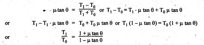
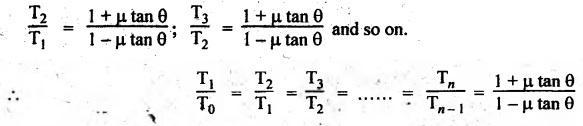
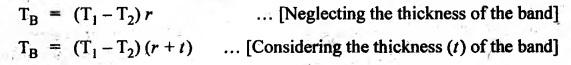
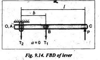
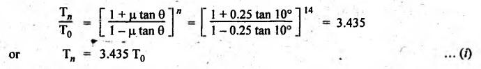
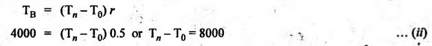
BAND AND BLOCK BRAKE As its name suggests, the band and block brake arrangement is a combination of both the band and the block brakes, as shown in Fig.9.13. The band is lined with a number of wooden blocks, each of which is in contact with the rim of the brake drum. When the brake is applied, the blocks are pressed against the drum. The advantage of using wooden blocks is that they provide higher coefficient of friction and they can be easily and economically replaced after being worn out. Let n = Number of blocks, T0 = Tension in the band on slack side, T1 = Tension on the tight side after one block, T2, T3, T4, etc. = Tensions on the tight side after second, third, fourth block, etc., Tn = Tension on the tight side after n blocks, μ = Coefficient of friction between the block and the drum, 20 2θ = Angle subtended by each block at the drum centre, and r = Radius of the drum. Consider one of the blocks (say first block) as shown in Fig.9.13(b). This block is in equilibrium under the action of the following forces: 1. Tension in the band on the slack side T0, 2. Tension in the band on the tight side between first and second block T1, 3. Normal reaction of the drum RN of the block, and 4. The frictional force, μ RN. Resolving the forces radially, we get Resolving the forces tangentially, we get Dividing equation (i) by (ii), we get Similarly, it can be proved for each of the blocks that So the ratio of tensions for all 'n' blocks is given by Braking torque on the drum is given by Example 9.7 In a band and block brake, the band is lined with 14 blocks, each of which subtends an angle of 20° at the drums centre. One end of the band is attached to the fulcrum of the brake lever and the other to a pin 150 mm from the fulcrum. Find the force required at the end of the lever 1 m long from the fulcrum to give a torque of 4 kN.m. The diameter of the brake drum is 1 m and the coefficient of friction between the blocks and the drum is 0.25. Given data: n = 14; 2θ = 20° or θ = 15°; a = 0; b = 150 mm = 0.15 m; l = 1 m; TB = 4 kN.m = 4000 N.m; d = 1 m or r = 0.5 m; μ = 0.25. Solution: Since b > a (here a = 0), so force P at C must act upwards. For the braking torque to be maximum, the band attached to fulcrum will experience slack side having tension T2 and the band attached at B will be tight side having tension T1, as shown in Fig.9.14. This is possible only when the drum rotates in the clockwise direction. We know that tension ratio for band and block brake, The braking torque is given by On solving equations (i) and (ii), we get T0 = 3285.42 N and T1 = 11285.42 N Taking moments about the fulcrum O, we get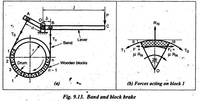


Theory of Machines: Unit III: Friction in Machine Elements : Tag: : Friction in Machine Elements - Theory of Machines - band and block brake
Related Topics
Related Subjects

Theory of Machines
ME3491 4th semester Mechanical Dept | 2021 Regulation | 4th Semester Mechanical Dept 2021 Regulation