Strength of Materials: Model Questions Papers
B.E/B.Tech degree examination, nov/dec 2016
Model Questions Papers - Strength of Materials
B.E/B.Tech degree examination, nov/dec 2016: Model Questions Papers - Strength of Materials
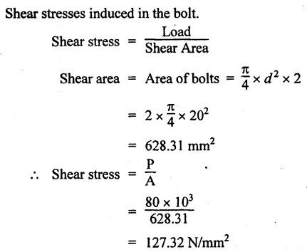
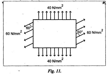
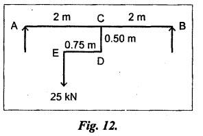
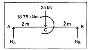
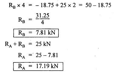
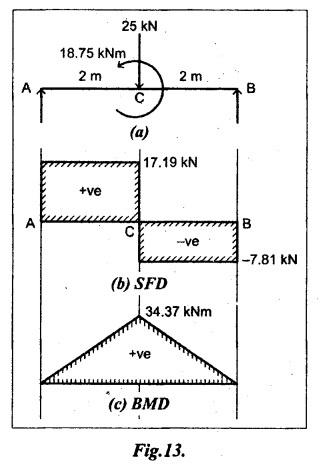
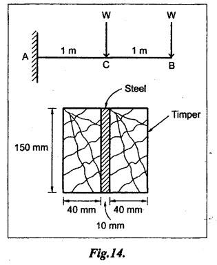
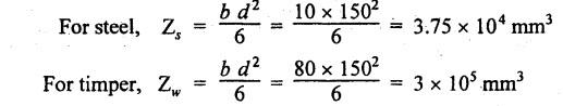
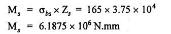
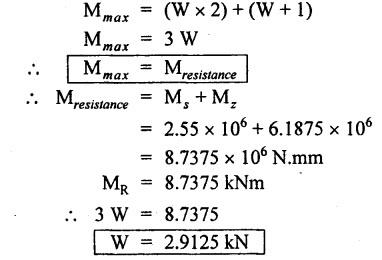
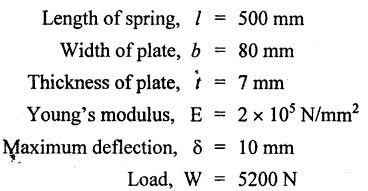
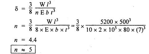
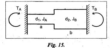
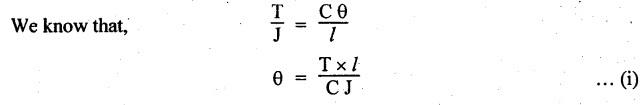
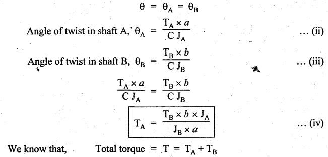
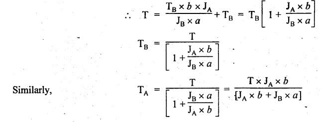
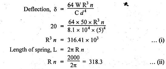
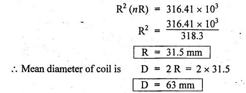
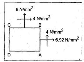
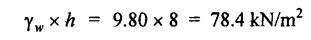
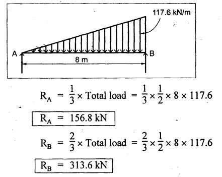
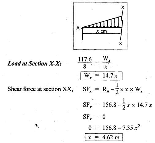
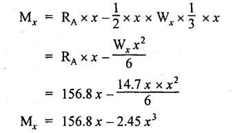
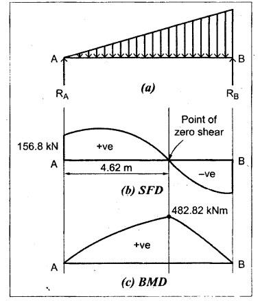
B.E/B.TECH DEGREE EXAMINATION, NOV/DEC 2016 Third Semester (Mech) CE 6306 - STRENGTH OF MATERIALS (Common to Mechatronics Engineering, Industrial Engineering and Management Industrial Engineering, Manufacturing Engineering, Mechanical Engineering (sandwich) and Material Science and Engineering) (Regulation 2013) Time: Three hours Maximum: 100 Marks Answer ALL Questions. Part A (10 x 2 = 20 marks) 1. Define Young's modulus. Ans. Refer Page no. 1.126, Question no. 9. 2. What do you mean by principal planes and principal stresses? Ans. Refer Page no. 1.192, Question no. 1. 3. Draw the shear force diagram and bending moment diagram for the cantilever beam carries uniformly varying load of zero intensity at the free end and W kN/m at the fixed end. Ans. Refer Page no. 2.12, Case (c). 4. List out the assumptions used to derive the simple bending equation. Ans. Refer Page no. 2.172, Question no. 3. 5. Define torsional rigidity. Ans. Refer Page no. 3.88, Question no. 10. 6. What is spring? Name the two important types of springs. Ans. Refer Page no. 3.140, Question no. 1. Types of springs: (i) Laminated spring (or) leaf springs (ii) Helical spring 7. List out the methods available to find the deflection of a beam. Deflection of beams may be determined analytically by the following methods. (i) Double Integration Method (ii) Macaulay's Method (iii) Moment Area Theorem Method (iv) Conjugate Beam Method 8. State Maxwell's reciprocal theorem. Ans. Refer Page no. 4.96, Section 4.1.32. 9. Name the stresses develop in the cylinder. Ans. Refer Page no. 5.63, Question no. 3. 10. Define radial pressure in thin cylinder. It is compressive in nature. Its magnitude is equal to fluid pressure on the inner wall and zero on the outer wall if it is open to atmosphere. Part B - (5 × 13 = 65 marks) 11. (a) (i) A compound tube consist of a steel tube 140 mm internal diameter and 160 mm external diameter and an outer brass tube 160mm internal diameter and 180 mm external diameter. The two tubes are of same length. The compound tube carries an axial compression load of 900 kN. Find the stresses and the load carried by each tube and the amount of its shortens. Take E for steel as 2 × 10⁵ N/mm2 and for a brass 1 × 10⁵ N/mm2. Ans. This question is similar to Example 1.23, Page no. 1.37. σs = 121.9 N/mm2; σb = 121.9 N/mm2 (ii) Two members are connected to carry a tensile force of 80 kN by a lap joint with two number of 20 mm diameter bolt. Find the shear stress induced in the bolt. Solution: Given: Tensile force, P = 80 kN = 80 × 103 N Diameter of bolt = 20 mm To find: Shear stresses induced in the bolt. Result: Shear stress induced in the bolts = 127.32 N/mm2 Or 11. (b) (i) A point in a strained materials is subjected to the stress as shown in Fig.11. Locate the principle plane and find the principle stresses. Ans. Refer Page no. 1.189, Example 1.87. 11. (b) (ii) A steel rod of 20 mm diameter passes centrally through a copper tube of 50 mm external diameter and 40 mm internal diameter. The tube is closed at the end by rigid plates of negligible thickness. The nuts are tightened lightly on the projecting parts of the rod. If the temperature of the assembly is raised by 50°C, calculate the stresses developed in copper and steel. Take E for steel as 2 × 10⁵ N/mm2 and copper as 1 × 10⁵ N/mm2 and a for steel and copper as 12 × 10-6 per °C and 18 × 10-6 per °C. Ans. Refer Page no. 1.66, Example 1.37. 12. (a) (i) A simply supported beam AB of length 5 m carries point loads of 8 kN, 10 kN, and 15 kN at 1.5 m and 2.5 m and 4 m respectively from left hand support. Draw shear force diagram and bending moment diagram. Ans. Refer Page no. 2.34, Example 2.12. (ii) A cantilever beam AB of length 2 m carries a uniformly distributed load of 12 kN/m over entire length. Find the shear stress and bending stress. If the size of the beam is 230 mm × 300 mm. Ans. Refer Page no. 2.166, Example 2.69. [OR] 12. (b) (i) Construct the SFD and BMD for the beam shown in Fig.12. Given: As shown in Fig.12. To draw: SFD and BMD Solution: Step (i): Find the moment and vertical force acting at point 'C' Mc = 25 × 0.75 ⸫ Mc = 18.75 kNm ⸫ Wc = 25 kN Step (ii): Taking moment about A SF calculation: SF at B = - RB = - 7.81 kN [Negative sign indicates right side upward force] SF at C = = - RB + 25 = - 7.81 + 25 = 17.19 kN SF at A = RA = 17.19 kN [+ve sign indicates left side upward force] BM calculation: BM at B = 0 BM at C = + RB × 2 + 18.75 = 7.81 × 2 + 18.75 = 34.37 kNm BM at A = 0 [⸫ BM at the supports should be zero] 12. (b) (ii) Two timper joist are connected by a steel plate are used as beam as shown in Fig.14. Find the load W. If the permissible stresses in steel and timper are 165 N/mm2 and 8.5 N/mm2 respectively. Given: Dimensions as shown in Fig.14. Permissible stresses, (i) Steel, σbs = 165 N/mm2 (ii) Timper, σbw = 8.5 N/mm2 To find: (i) Moment of resistance of composite section (ii) Load on beam (W) Solution: Section modulus [Refer Table 2.1] Moment of resistance of timper section Moment of resistance of steel section Load on beam (W): To avoid failure, moment due to external load is equal to moment of resistance. Result: (i) MR = 8.7375 kNm (ii) W = 2.9125 kN 13. (a) (i) A solid shaft has to transmit the power 105 kW at 2000 rpm. The maximum torque transmitted in each revaluation exceeds the mean by 36%. Find the suitable diameter, if the shear stress is not to exceed 75 N/mm2 and maximum angle of twist is 1.5° in a length of 3.30 m and G = 0.80 × 10³ N/mm2. Ans. This question is similar to Example 3.20, Page no. 3.28. (D = 100 mm) (ii) A laminated spring carries a central load of 5200 N and it is made of 'n' number of plates, 80 mm wide, 7 mm thick and length 500 mm. Find the number of plates, if the maximum deflection is 10 mm. Let E = 2 × 10⁵ N/mm2. Given: To find: (a) Number of plates We know that, deflection equation for laminated spring Result: Number of plates, n = 5 [OR] 13. (b) (i) A stepped solid circular shaft is built in at its ends and subject to an external applied torque T at the shoulder as shown in Fig.15. Determine the angle of rotation θ of the shoulder section when T is applied. Given: Dimensions as shown in Fig.15. In this case, angle of twist is same for each section. TA substitute in equation (iii), Substitute TA (or) TB value in equation (ii) (or) (iii). 13. (b) (ii) A closed coiled helical spring is to be made out of 5 mm diameter wire 2 m long so that it deflects by 20 mm under an axial load of 50 N. Determine the mean diameter of the coil. C = 8.1 × 10⁴ N/mm2. Given: d = 5 m L = 2 m δ = 20 mm W = 50 N C = 8.1 × 10⁴ N/mm2 To find: Mean diameter of the coil (D) Solution: We know that, Substituting the nR value in equation (i), Result: D = 63 mm 14 (a) Cantilever of length I carrying UDL W kN per unit run over whole length. Derive the formula to find the slope and deflection at the free end by double integration method. Calculate the deflection, if W = 20 kN/m, I = 2.30 m and EI = 12000 kNm2. Ans: Refer Page no. 4.8, Section 4.1.7. Maximum downward deflection at free end [OR] 14. (b) (i) Derive the formula to find the deflection of a simply supported beam with point load W at the centre by moment area method. Ans. Refer Page no. 4.33, Section 4.1.18. (ii) A simply supported beam of span 5.80 m carries a central point load of 37.50 kN. Find the maximum slope and deflection, let EI = 40000 kNm2. Use conjugate beam method. Ans. Refer Page no. 4.68, Example 4.6. 15. (a) (i) Calculate change in diameter, change in length and change in volume of a thin cylindrical sheet 100 cm diameter, 1 cm thick, 5 m long, when subjected to internal pressure 3 N/mm2. Take the value of E = 2 × 10⁵ N/mm2 and Poisson's ratio = 0.30. [OR] (b) Calculate the thickness of metal necessary for a cylindrical shell of internal diameter 160 mm to withstand in internal pressure of 25 MN/m2, if maximum permissible shear stress is 125 MN/m2. Ans. Refer Page no. 5.46, Example 5.28. Part C (1 x 15 = 15 Marks) 16. (a) The intensity of resultant stress on a plane AB at a point in a material under stress is 8 N/mm2 and it is inclined at 30° to the normal to that plane. The normal component of stress on another plane BC at right angles to plane AB is 6 N/mm2. Determine the following: (i) The resultant stress on the plane BC (ii) The principal stresses and their directions (iii) The maximum shear stresses Given: Ans. This question is similar to Example 5.25. (i) Resultant stress = 7.21 N/mm2 (ii) Major principal stress = 10.49 N/mm2 (iii) Minor principal stress = 2.43 N/mm2 (iv) Maximum shear stress = 4.02 N/mm2 [OR] (b) A water tank vertical wall is stiffened by vertical beam and the height of the tank is 8 m. The beams are spaced at 1.5 m centre. If the water reaches the top of the tank, calculate the maximum bending moment on a vertical beam. Sketch the shear force and bending moment diagrams. Unit weight of water = 9.8 kN/m3. Given: Height of tank = 8 m Spacing of vertical beams = 1.5 m Unit weight of water = 9.8 kN/m3 To find: (i) Maximum bending moment (ii) Sketch the SFD and BMD Solution: The water pressure at the top is zero. At the base i.e., 8 m below the free surface. The horizontal loading on a vertical beam will be zero per meter run at the top. Increasing uniformly to 1.5 × 78.4 = 117.6 kN/m at the bottom. Support reaction (A & D). Maximum BM calculation: Point of zero shear, take a section XX at x m distance from A. Maximum bending moment at section X-X: Maximum BM at point of zero shear i.e., x = 4.62 m Mmax = 156.8 × 4.62 - 2.45 × 4.623 = 482.82 kNm Result: Maximum BM = 482.82 kNm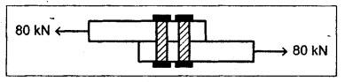


Ans. Refer Page no. 5.13, Example 5.8.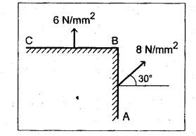
Strength of Materials: Model Questions Papers : Tag: : Model Questions Papers - Strength of Materials - B.E/B.Tech degree examination, nov/dec 2016
Related Topics
Related Subjects
Strength of Materials
CE3491 4th semester Mechanical Dept | 2021 Regulation | 4th Semester Mechanical Dept 2021 Regulation