Strength of Materials: Model Questions Papers
B.E/B.Tech degree examination, nov/dec 2014
Model Questions Papers - Strength of Materials
B.E/B.Tech degree examination, nov/dec 2014: Strength of Materials: Model Questions Papers
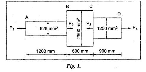
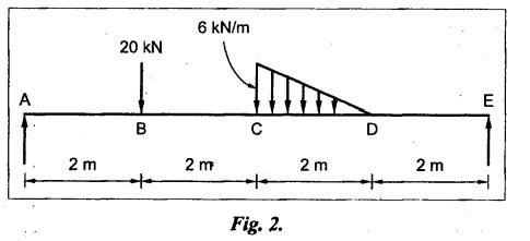
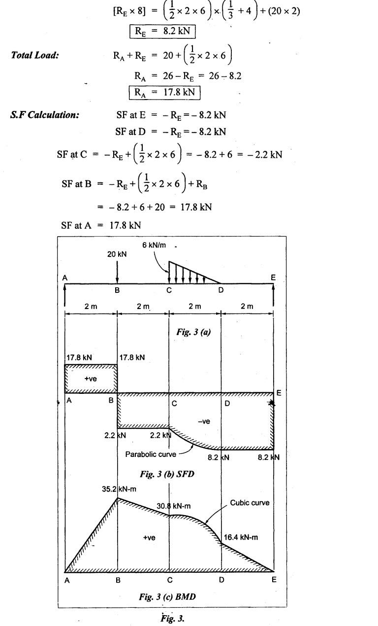
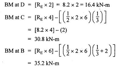
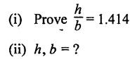
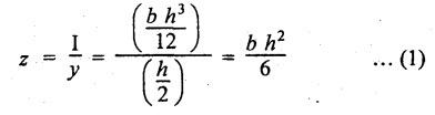
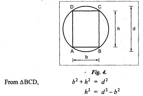
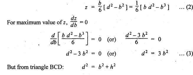
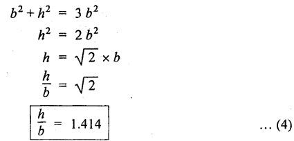
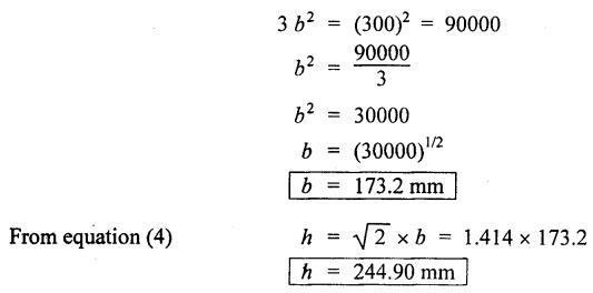
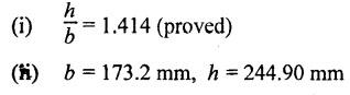
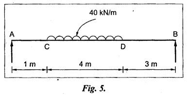
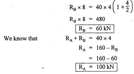
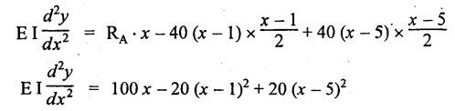
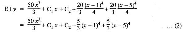
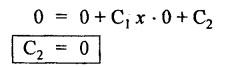
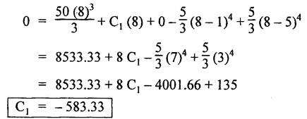
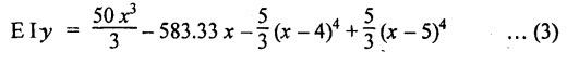
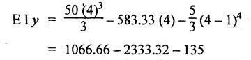
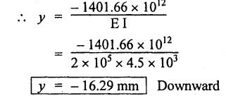
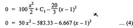
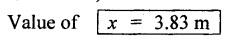
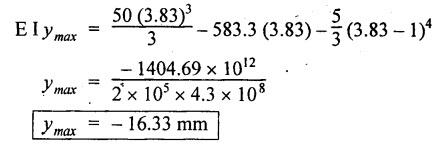
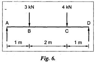
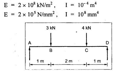
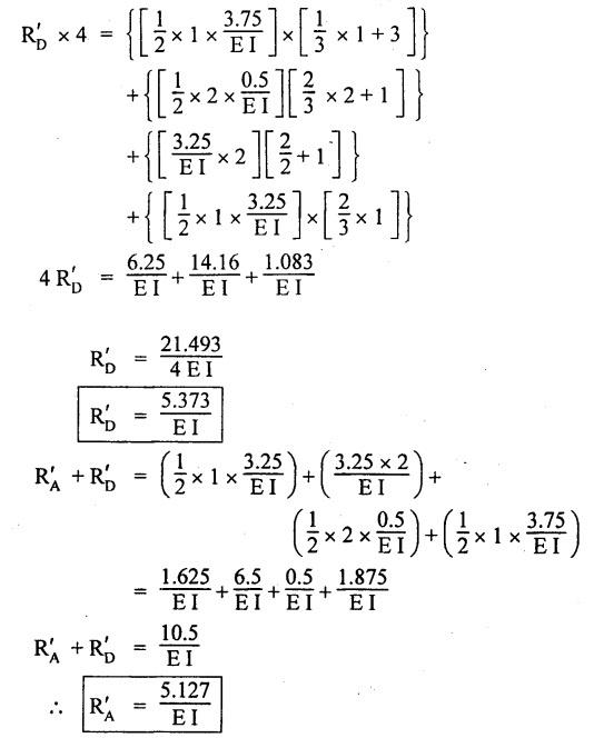
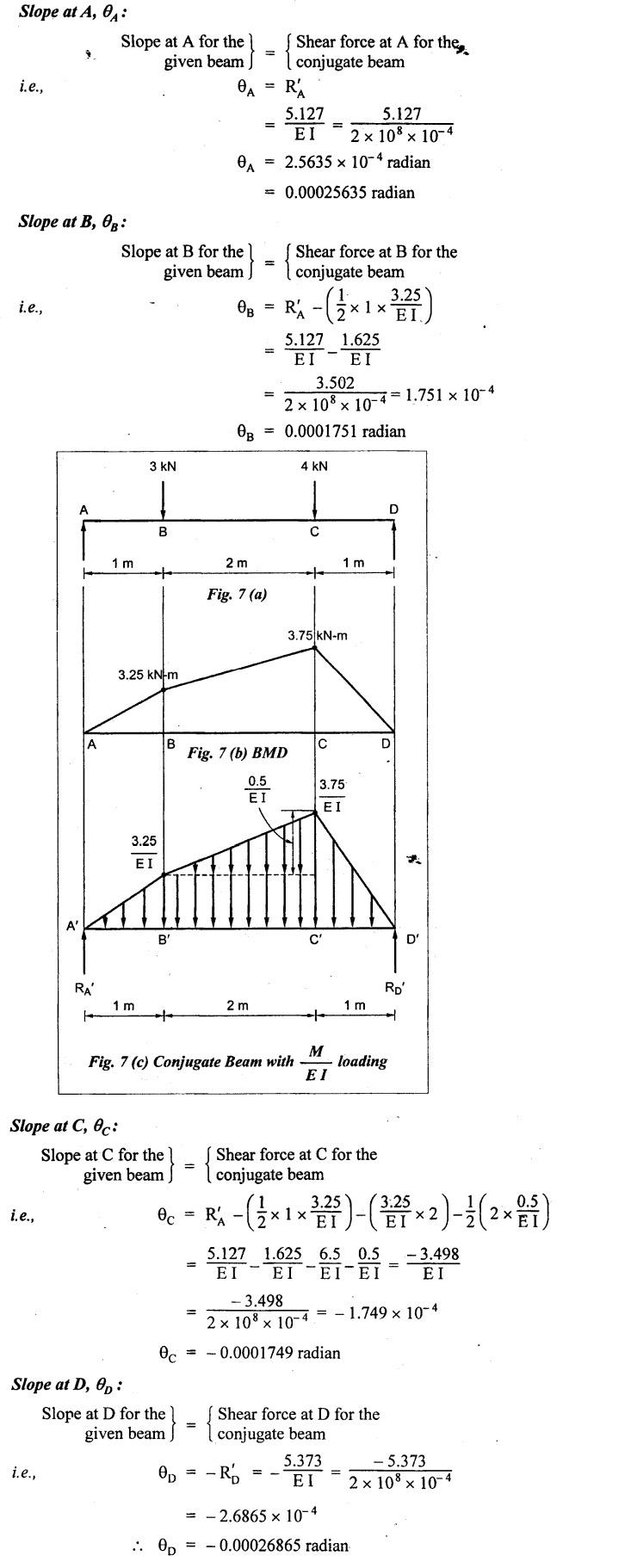
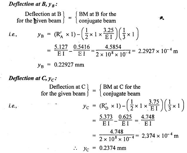
B.E/B.TECH DEGREE EXAMINATION, NOV/DEC 2014 Third Semester (Mech) STRENGTH OF MATERIALS (Common to Mechatronics Engineering, Industrial Engineering and Management Industrial Engineering, Manufacturing Engineering, Mechanical Engineering (sandwich) and Material Science and Engineering) Time: Three hours (Regulation 2013) Answer ALL Questions Maximum: 100 Marks Part A (10 x 2 = 20 marks) 1. Derive a relation for change in length of a bar hanging freely under its our weights. Ans. Refer Page no. 1.5, Section 1.1.16. 2. Write the relationship between shear modulus and Young's modulus of elasticity. Ans. Refer Page no. 1.127, Question no. 17. 3. Draw SFD for a 6 m cantilever beam carrying a clockwise moment of 6 kN-m at free end. There is no vertical force through the beam. ⸫ Shear force is zero. 4. What are flitched beams? Ans. Refer Page no. 2.172, Question no. 6. 5. What is meant by torsional rigidity? Ans. Refer Page no. 3.88, Question no. 10. 6. Differentiate open coiled and closely coiled helical springs. Ans. Refer Page no. 3.141, Question no. 5. 7. What are the limitations of double integration method? Ans. The limitations of double integration methods are: 1. This method is used only for single load. 2. This method for finding slope and deflection is very laborious. 8. Define strain energy. Ans. Refer Page no. 4.103, Section 4.2. 9. What is meant by circumferential stress? Ans. Refer Page no. 5.2, Section (a). 10. Write down Lame's equations. Ans. Refer Page no. 5.63, Question no. 6. Part B - (5 × 16 = 80 marks) 11. (a) (i) Derive an expression for change in length of a circular bar with uniformly varying diameter and subjected to an axial tensile load 'P'. (8) Ans. Refer Page no. 1.12, Section 1.1.19. (ii) A member is subjected to point loads as shown in Fig.1. Calculate the force P2, necessary for equilibrium if P1 = 45 kN, P3 = 450 kN and P4 = 130 kN. Determine total elongation of the member, assuming the modulus of elasticity to be E = 2.1 × 10⁵ N/mm2. Ans. Refer Page no. 1.24, Example 1.15. (i) The force P2 = 365 kN (ii) Total elongation of the member (δl) = 0.4914 mm [OR] (b) A metallic bar 300 mm (x) × 100 mm (y) × 40 mm (z) is subjected to a force of 5 kN (tensile), 6 kN (tensile) and 4 kN (tensile) along x, y and z directions respectively. Determine the change in the volume of the block. Take E = 2 × 10⁵ N/mm2 and Poisson's ratio = 0.25. Ans. Refer Page no. 1.110, Example 1.56. The change in the volume of block [dv] = 5.649 mm3 12. (a) Draw SFD and BMD and find the maximum bending moment for the beam given in Fig.2. Given: As shown in Fig.2. To find: (i) Draw SFD and BMD (ii) Maximum BM Solution: Taking moment about A, Join all the values by corresponding parabolic curves and lines shown in Fig.3(b). BM calculation: BM at E = 0 BM at A = 0 Join the values between C and D by cubic curve and all other values by straight line. The maximum bending moment at B = 35.2 kN-m. Result: (i) The maximum BM value is 35.2 kN-m. (ii) The SFD and BMD are as shown in Fig.3(b) and (c). [OR] 12. (b) Prove that the ratio of depth to width of the strongest beam that can be cut from a circular log of diameter ‘d' is 1.414. Hence calculate the depth and width of the strongest beam that can be cut out of a cylindrical log of wood whose diameter is 300 mm. Given: Diameter of log = d To find: Let ABCD be the strongest rectangular section which can be cut of the cylindrical log. Let b = Width of strongest section d = Depth of strongest section Now section modulus of the rectangular section In the above equation, b and h are variable. Substituting the value of h2 in equation (1), we get Substituting the value of d2 in equation (3), we get. Numerical Part: Given that d = 300 mm But for equation (3) d2 = 3b2 3b2 = d2 Result: 13. (a) Derive torsion equation. Ans. Refer Page no. 3.2, Section 3.1.3. Refer Page no. 3.6, Section 3.1.6. [OR] 13. (b) The stiffness of a close-coiled helical spring is 1.5 N/mm of compression under a maximum load of 60 N. The maximum shearing stress produced in the wire is 125 N/mm2. The solid length of the spring (when the coils are touching) is given as 50 mm. Find: (i) The diameter of wire (ii) The mean diameter of the coils (iii) Number of coils required. Take C = 4.5 × 10⁴ N/mm2 Ans. Refer Anna University Solved Question Paper, Nov/Dec 2006, Question no. 13 (b). 14. (a) Determine the deflection of the beam at its midspan and also the position of maximum deflection and maximum deflection. Take E = 2 × 10⁵ N/mm2 and I = 4.3 × 104 mm4. Use Macaulay's method. The beam is given in Fig.5. Given: Length of beam, L = 8 m u.d.l, W = 40 kN/m E = 2 × 10⁵ N/mm+ I = 4.3 × 108 mm4 To find: (i) Deflection at the centre, y (ii) Position of maximum deflection, x (iii) Maximum deflection, ymax Solution: Taking moment about A, Now applying Macaulay's method, The B.M at any section at a distance x from end A is given by Integrating the above equation, we get Integrating again, we get where C1 and C2 are constants of integration. Their values are obtained from boundary conditions which are: (i) At x = 0, y = 0 (ii) At x = 8 m, y = 0 (i) Substituting x = 0, y = 0 in equation (2) (ii) Substituting x = 8 and y = 0 in equation (2) Substituting the value of C1 and C2 in equation (2), we get (a) Deflection at the centre, y By substituting x = 4 m in equation (3), we get the deflection at centre. = -1401.66 KN-m3 = -1401.66 × 103 N-m3 = 1401.66 × 103 × 109 N-mm3 = - 1401.66 × 1012 N-mm3 (b) Position of maximum deflection, x: The maximum deflection is likely to be between C and D. For maximum deflection, the slope dy/ dx should be zero. Hence equating the slope given by equation (1) to zero, we get The above equation is solved by trial and error method. Let x = 1, then R.H.S of equation (4) = 50 - 583.33 - 6.667 × 0 = - 533.33 Let x = 2, then R.H.S of equation (4) = 50 × 4 - 583.33 - 6.667 × 1 = -390.00 Let x = 3, then R.H.S of equation (4) = 50 × 9 - 583.33 - 6.667 × 8 = 136.69 Let x = 4, then R.H.S = 50 × 16 - 583.33 – 6.667 × 27 = 36.58 In equation (4), when x = 3 then R.H.S is negative (or) when x = 4 then R.H.S is positive. Hence exact value of x lies between 3 and 4. The R.H.S is approximately zero in comparison of the three terms (ie., 733.445, 583.33 and 151.1) Hence maximum deflection will be at a distance of 3.83 m from a support A. (c) Maximum deflection, y max Substituting x = 3.83 m in equation (3), Result: (i) Deflection at the centre, y = -16.29 mm (ii) Position of maximum deflection, x = 3.83 m (iii) Maximum deflection, ymax =-16.33 mm [OR] 14. (b) Using conjugate beam method, determine the (i) Slope at each end and under each load (ii) Deflection under each load for the beam given in Fig.6. Take E = 2 × 10⁵ N/mm2 and I = 108 mm4. Given: To find: (i) Slope at each end and under each load (ii) Deflection under each load Solution: Taking moments at A, RD × 4 = [4 × 3] × [3 × 1] ⸫ RD = 3.75 kN RA + RD = 3 + 4 RA = 3.25 kN BM Calculation: BM at D = 0 BM at C = (3.75 × 1) = 3.75 kN-m BM at B = (3.75 × 3) - (4 × 2) = 3.25 kN-m BM at A = 0 Taking moment about A, (i) Slopes at A, B, C D (ii) Deflection under each load (at B and C) Result: (i) Slope at A, θA = 0.00025635 radian θB = 0.0001751 radian θC = -0.0001749 radian θD = -0.00026865 radian (ii) Deflection at B, yв = 0.22927 mm At C, yC = 0.2374 mm 15. (a) Derive relations for change in dimensions and change in volume of a thin cylinder subjected to internal pressure P. Ans. Refer Page no. 5.4, Section 5.1.3. [OR] (b) Find the thickness of metal necessary for a thick cylindrical shell of internal diameter 160 mm to withstand an internal pressure of 8 N/mm2. The maximum hoop stress in section is not to exceed 35 N/mm2. Ans. Refer Page no. 5.43, Example 5.28. The thickness of shell, t = 20.96 mm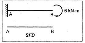


Strength of Materials: Model Questions Papers : Tag: : Model Questions Papers - Strength of Materials - B.E/B.Tech degree examination, nov/dec 2014
Related Topics
Related Subjects
Strength of Materials
CE3491 4th semester Mechanical Dept | 2021 Regulation | 4th Semester Mechanical Dept 2021 Regulation