Strength of Materials: Model Questions Papers
B.E/B.Tech degree examination, may/june 2013
Model Questions Papers - Strength of Materials
B.E/B.Tech degree examination, may/june 2013: Strength of Materials: Model Questions Papers
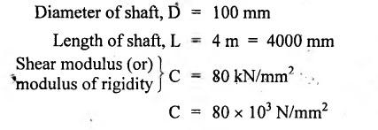
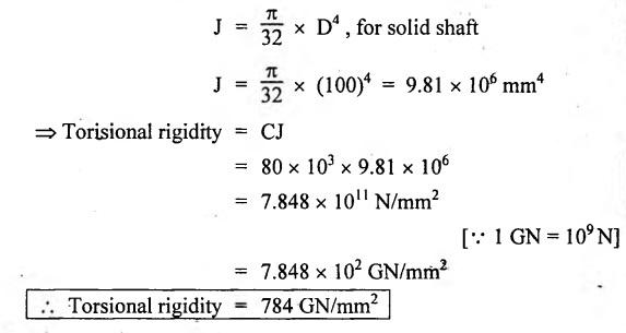
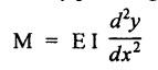
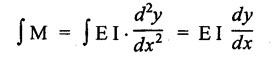
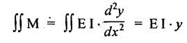
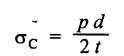
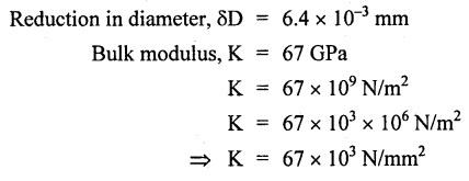
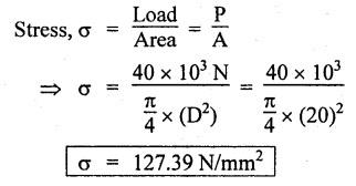
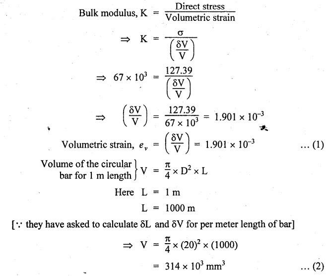
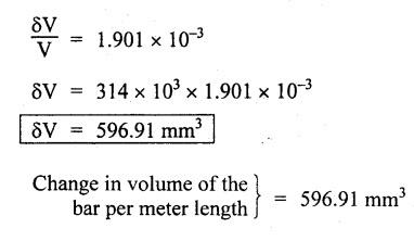
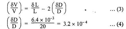
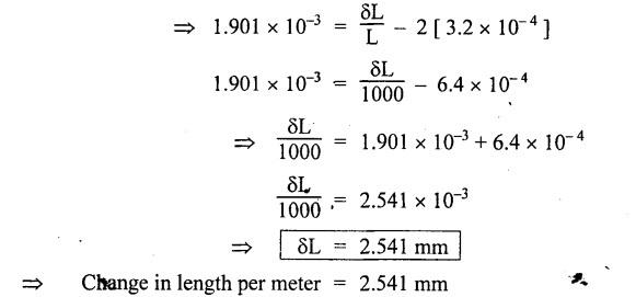
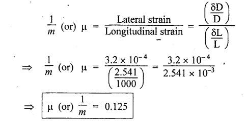
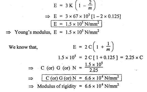
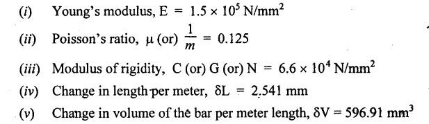
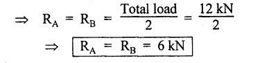
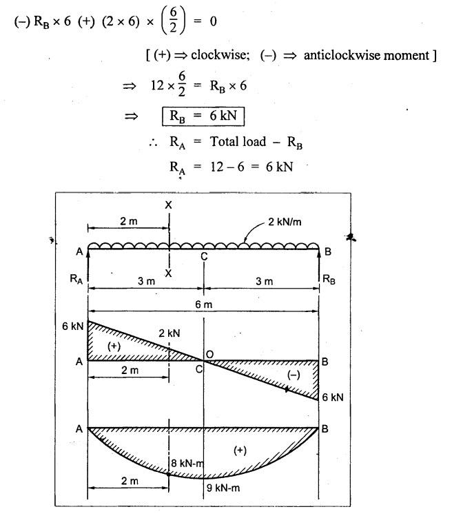
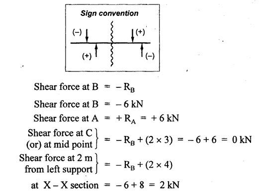
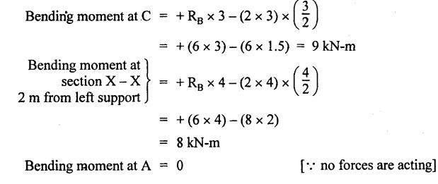
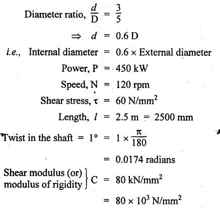
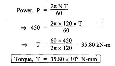
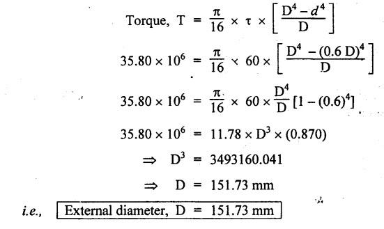
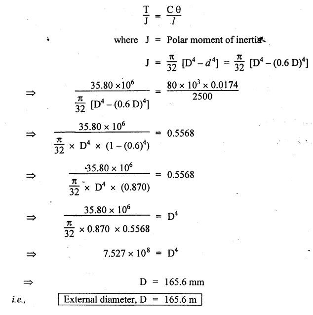
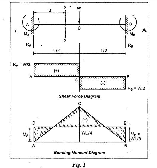
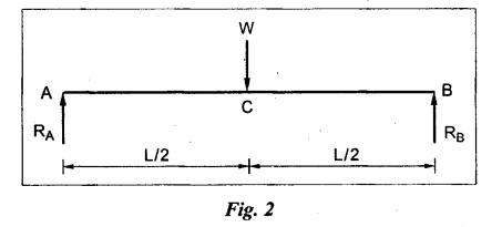
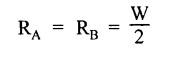
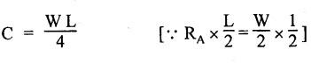
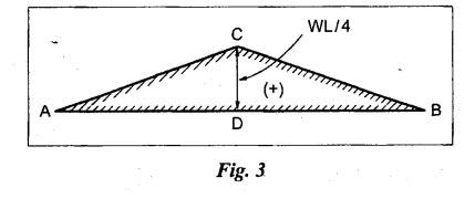
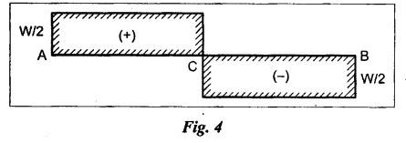
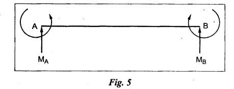
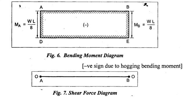
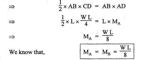
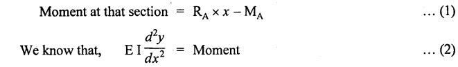
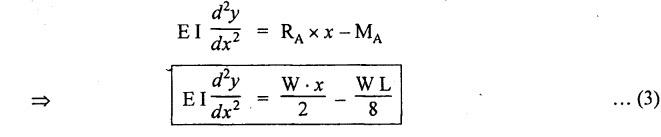
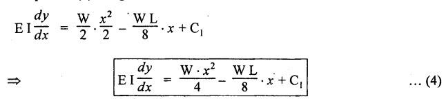
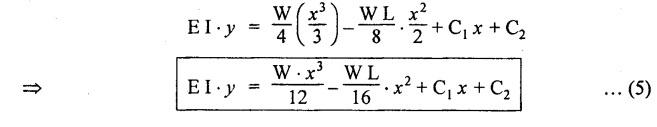
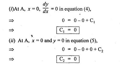
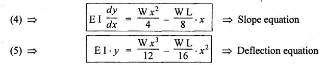
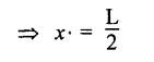
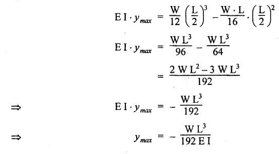
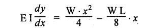
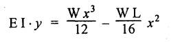
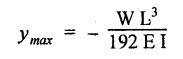
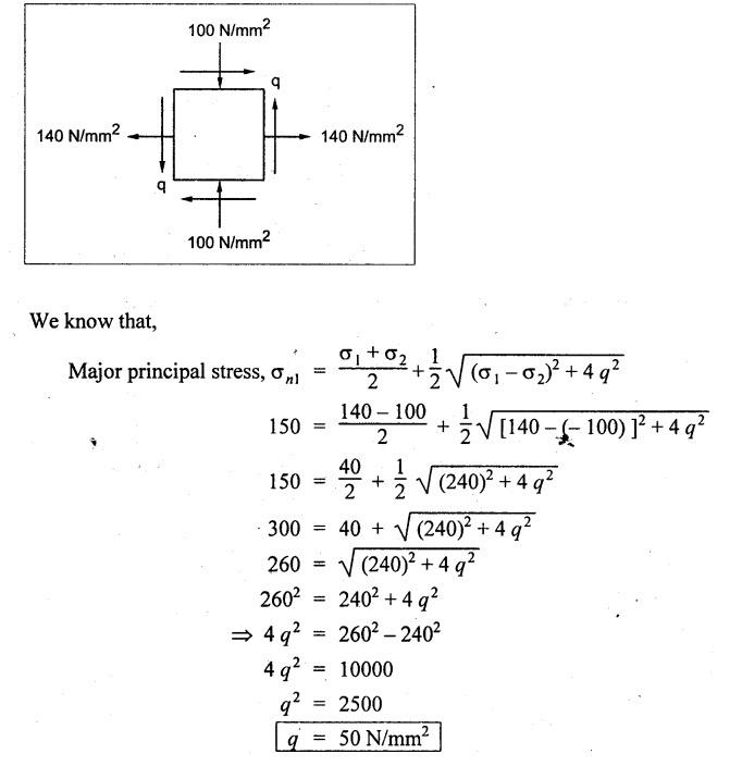
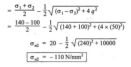
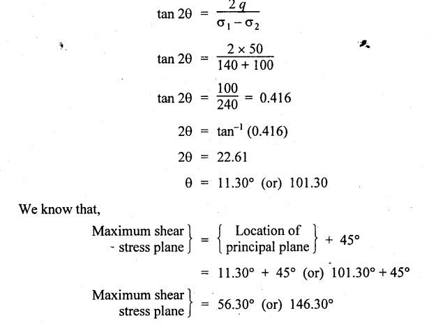
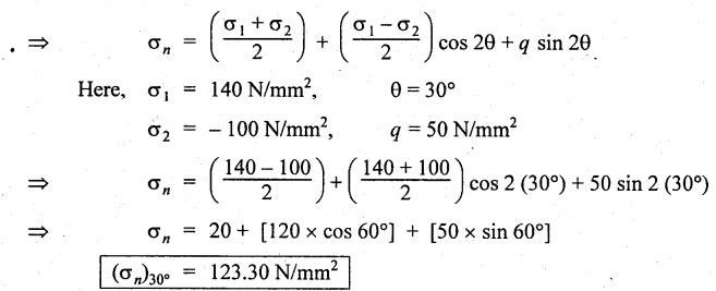
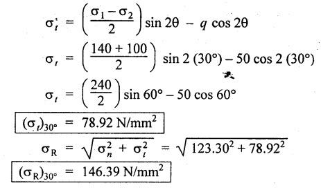
ANNA UNIVERSITY B.E/B.TECH DEGREE EXAMINATION, MAY/JUNE 2013 Fourth Semester - Mechanical Engineering STRENGTH OF MATERIALS (Common to Automobile Engineering and Production Engineering) (Regulation 2008/2010) (Common to PTME 2254 Strength of Materials for B.E. (Part-Time) Third Semester Mechanical Engineering-Regulation 2009) Answer ALL Questions. Part A (10 × 2 = 20 marks) Time: Three hours 1. Define Hooke's law. Ans. Refer Page no. 1.125, Question no. 3. 2. Define the term modulus of resilience. Ans. Refer Page no. 1.128, Question no. 24. 3. Define point of contra flexure. Ans. Refer Page no. 2.122, Question no. 25. 4. What is meant by shear flow? In the case of any section i.e., symmetrical and unsymmetrical, the rate of shear stress varies from point to point. The flow of shear force resisting the load always moves from the end of the section to the point of application of load. This phenomenon is known as shear flow. 5. Compute the torsional rigidity of a 100 mm diameter, 4 m length shaft C = 80 kN/mm2. Given: To find: Torsional rigidity = CJ Solution: Torsional rigidity = CJ where J = Polar moment of inertia' 6. Write any four differences between open and closed coiled springs. Ans. Refer Page no. 3.141, Question no. 5. 7. Describe the double integration method. The bending moment at any point is given by Integrating the above equation, we get slope equation. Again integrating the above equation, we get deflection equation. Hence integrating bending moment equation once gives slope at any point and integrating bending moment equation twice gives the deflection at any point. This is known as double integration method. 8. What is slenderness ratio of a column? NOT IN SYLLABUS 9. Define principal stress and principal plane. Ans. Refer Page no. 1.192, Question no. 1. 10. Define circumferential or Hoop stress. Ans. Refer Page no. 5.1, Section 5.1.2. The stress in the circumferential direction due to tendency of bursting the cylinder along the longitudinal axis is called circumferential stress (or) hoop stress. where, σc = Circumferential stress p - Internal fluid pressure d - Diameter of thin cylinder t - Thickness of thin cylinder PART B-(5 × 16 = 80 marks) 11. (a) A reinforced concrete column 500 mm × 500 mm in section is reinforced with 4 steel bars of 25 mm diameter; one in each corner, the column is carrying a load of 1000 kN. Find the stresses in the concrete and steel bars. Take E for steel = 210 × 103 N/mm2 and E for concrete = 14 × 103 N/mm2. Ans. Refer Page no. 1.122, Example no. 1.62. [OR] 11. (b) A solid circular bar of diameter 20 mm when subjected to an axial tensile load of 40 kN, the reduction in diameter of the rod was observed as 6.4 × 10⁻³ mm. The bulk modulus of the material of the bar is 67 GPa. Determine the following: (i) Young's modulus, (ii) Poisson's ratio, (iii) Modulus of rigidity, (iv) Change in length per metre and (v) Change in volume of the bar per metre length. Given: Diameter of bar, D = 20 mm Axial tensile load = 40 kN P = 40000 N To find: (i) Young's modulus, E (ii) Poisson's ratio, μ (or) 1/m (iii) Modulus of rigidity, C (iv) Change in length per meter, δL (v) Change in volume of the bar per meter length Solution: We know that, We also know that, Using equations (1) and (2), Volumetric strain for circular bar is given by Using equations (4) in (3), Poisson's ratio is given by From the relationship, Result: 12. (a) A simply supported beam of span 6 m is carrying a uniformly distributed load of 2 kN/m over the entire span. Calculate the magnitude of shear force and bending moment at every section, 2 m from the left support. Also draw shear force and bending moment diagrams. Given: Length of the beam = 6 m UDL intensity = 2 kN/m To draw: SFD and BMD Solution: Since the loading symmetrical on both sides, Total load on beam = Intensity of load × Length = 2 kN/m × 6m = 12 kN [OR] To find the reactions: RA & RB Total load = 2 kN/m × 6m = 12 kN Taking moment about A, we get Shear force calculations: Bending moment calculations: Bending moment at B = 0 [since no forces are acting to the right side of B in beam] Result: (i) The SFD and BMD are shown in the Fig. (ii) Shear force at 2 m from left support, A = 2 kN (iii) Bending moment at 2 m from left support, A = 8 kN-m [OR] 12. (b) State the assumptions made in the theory of simple bending and derive the simple bending equation. Ans. Refer Page no. 2.129, 2.130, Section 2.2.2 and 2.2.3. 13. (a) A hollow shaft with diameter ratio 3/5 is required to transmit 450 kW at 120 rpm. The shearing stress in the shaft must not exceed 60 N/mm2 and the twist in a length of 2.5 m is not to exceed 1°. Calculate the minimum external diameter of the shaft. C = 80 kN/mm2. Given: To find: External diameter of hollow shaft. Solution: We know that, First case: Considering shear stress (τ) Second case: Consider the angle of twist Result: Hence adopt the greater diameter values i.e., external diameter, D= 165.6 mm. [OR] 13. (b) Derive a relation for deflection of a closely coiled helical spring subjected to an axial downward load W. Ans. Refer Page no. 3.92, Section 3.2.4. 14. (a) A beam of span length L is loaded at its midspan with a point load W. If both the ends are fixed under supports are at same level, find out the slope and deflection for the beam. Given: The beam with fixed supports is shown in Fig.1. To find: Slope and deflection for the fixed beam. Solution: Let MA = Fixed end moment at A MB = Fixed end moment at B RA = Reaction at A RB = Reaction at B The above fixed beam is analysed in two ways. (i) A simply supported beam subjected to vertical load 'W' at mid-span We know that, due to symmetry of loading the reaction at supports is given by and, the bending moments at A and B are zero. (since the supports are simply supported). Bending moment at mid-span at ⸫ The bending moment diagram for the Fig.2 is and SFD is (ii) A simply supported beam subjected to end moments only We know that, due to symmetry of loading, the end moments MA and MB will be equal. Therefore bending moment diagram will be For equilibrium, the area of bending moment diagram due to vertical load (Fig.3) should be equal to the area of bending moment diagram due to end moments. (Fig.6) Equating the two areas of bending moment, we get Area of triangle ABC = Area of rectangle ABED Since no-load is acting on the second analysis, the shear force is zero and hence SFD is also zero. Hence combining the SFD and BMD for the two cases, we get Fig.1. Hence, we get two points of contraflexure at a distance of L/4 from the fixed ends. To find slope and deflection Consider any section between AC at a distance x. Then the moment at that section is given by Equating (1) and (2), Integrating the above equation (3), we get The above equation is the slope equation. Again integrating equation (4), we get The above equation is the deflection equation. To find the constants C1 and C2, apply the boundary conditions. Using C1 = C2, in equations (4) and (5), we get The above equations gives us the slope and deflection of the beam at any point. To find maximum deflection: The deflection is maximum at the centre of the beam i.e., under the point load. Using x = L/2 in deflection equation, we get Minus sign indicates that the deflection is downwards. Result: (i) Slope at any point is given by, (ii) Deflection at any point is given by (iii) Maximum deflection at centre is given by [OR] 14. (b) Derive the Euler's formula for a long column with one end fixed and the other is free. Write the assumptions also. NOT IN SYLLABUS 15. (a) A thin cylinder is 3.5 m long, 90 cm in diameter, and the thickness of metal is 12 mm. It an internal pressure of is subjected to 2.8 N/mm2. Calculate the change in dimensions of the cylinder and the maximum intensity of shear stress induced. Given E = 200 GPa and Poisson's ratio = 0.3. Ans. Refer Page no. 5.13, Example no. 5.8. Result: Longitudinal stress, σa = 52.5 N/mm2 Hoop stress, σc = 105 N/mm2 (Maximum shear stress) Change in diameter, δd = 0.40 mm Change in length, δl = 0.36 mm Change in volume, δV = 2221037.28 mm3 [OR] 15. (b) The normal stress at a point on two mutually perpendicular planes are 140 MPa (Tensile) and 100 MPa (Compressive). Determine the shear stress on these planes if the maximum principal stress is limited to 150 MPa (Tensile). Determine also the following: (i) Minimum principal stress, (ii) Maximum shear stress and its plane and (iii) Normal, shear and resultant stresses on a plane which is inclined at 30° anticlockwise to X plane. Given: To find: (i) Shear stress, q (ii) Minimum principal stress, σn2 and its position (iii) Normal stress (σn)30, shear stress (σt)30 and (σR) which is inclined at 30° anticlockwise with X-plane (iv) Maximum shear stress and its plane Solution: (i) To find shear stress (q): (ii) We know that, Minimum (or) minor principal stress σn2 (iii) Maximum shear stress (σt)max Location of maximum shear stress plane: We know that, location of principal plane is given by (iv) To find σn, σt and σR at 30° inclined plane We know that, on any inclined plane, normal stress, σ,, is given by We know that, shear stress on inclined plane is given by, Result: (i) Shear stress, q = 50 N/mm2 (ii) Minimum principal stress, σn2 = - 110 N/mm2 (iii) Maximum shear stress, (σt)max = 130 N/mm2 and maximum shear stress plane = 56.30° (or) 146.30° (iv) Normal stress at 30° plane, (σn)30° = 123.30 N/mm2 Shear stress at 30° plane, (σt)30° = 78.92 N/mm2 Resultant stress at 30° plane, (σR)30° = 146.39 N/mm2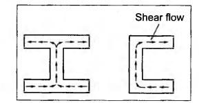


Strength of Materials: Model Questions Papers : Tag: : Model Questions Papers - Strength of Materials - B.E/B.Tech degree examination, may/june 2013
Related Topics
Related Subjects
Strength of Materials
CE3491 4th semester Mechanical Dept | 2021 Regulation | 4th Semester Mechanical Dept 2021 Regulation