Strength of Materials: Model Questions Papers
B.E/B.Tech degree examination, may/june 2007
Model Questions Papers - Strength of Materials
B.E/B.Tech degree examination, may/june 2007: Strength of Materials: Model Questions Papers
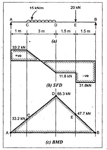
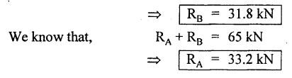
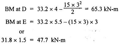
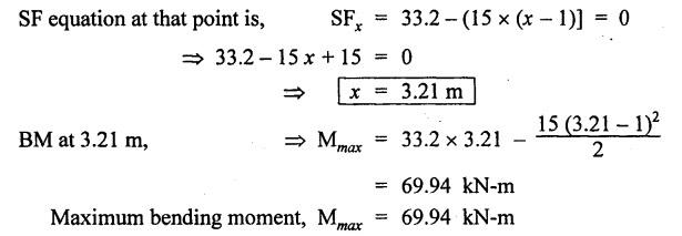
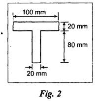
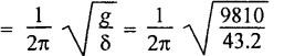
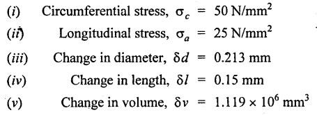
ANNA UNIVERSITY B.E/B.TECH DEGREE EXAMINATION, MAY/JUNE 2007 Fourth Semester - Mechanical Engineering STRENGTH OF MATERIALS (Common to Mechanical Engineering/Mechatronics Engineering/Metallurgical Engineering/Production Engineering) (Regulation 2004) Time: Three hours Answer ALL Questions. Maximum: 100 Marks Part A (10 × 2 = 20 marks) 1. Give the relation between modulus of elasticity and modulus of rigidity. Ans. Refer Page no. 1.127, Question no. 17. 2. Write the concept used for finding stresses in compound bars. Ans. Refer Page no. 1.34 Section 1.1.25. 3. Write down relations for maximum shear force and bending moment in case of a cantilever beam subjected to uniformly distributed logd running over entire span. Maximum shear force = wl Maximum bending moment = wl2/2 4. Mention any two assumptions made in the theory of simple bending. Ans. Refer Page no. 2.172, Question no. 3. 5. What do you mean by torsional rigidity of a shaft? Also, give the expression for finding power transmitted by a shaft. Ans. Refer Page no. 3.86, Question no. 4 and Page no. 3.88, Question no. 10. The product of modulus of rigidity (C) and polar moment of inertia (J) of a shaft is known as torsional rigidity or stiffness of a shaft. 6. How will you find maximum shear stress induced in the wire of a close- coiled helical spring carrying an axial load? Ans. Refer Page no. 3.143, Question no. 14. 7. What is the maximum deflection in a simply supported beam subjected to uniformly distributed load over the entire span? Ans. Refer Page no. 4.25, Equation no. 4.43. 8. What is crippling load? Give the effective length of columns when both ends hinged and when both ends fixed. NOT IN SYLLABUS 9. A cylindrical pipe of diameter 1.5 m and thickness 1.5 cm is subjected to an internal fluid pressure of 1.2 N/mm2. Determine the longitudinal stress developed in the pipe. Ans. Refer Page no. 5.8, Example 5.1... [Longitudinal stress = 30 N/mm2] 10. How will you find major principal stress and minor principal stress? Also mention how to locate the direction of principal planes. Ans. 11. (a) A mild steel rod of 20 mm diameter and 300 mm long is enclosed centrally inside a hollow upper tube of external diameter 30 mm and internal diameter of 25 mm. The ends of the tube and rods are brazed together and the composite bar is subjected to an axial pull of 40 kN. If E for steel and copper is 200 GN/m2 and 100 GN/m2 respectively, find the stresses developed in the rod and tube. Also, find the extension of the rod. Ans. Refer Page no. 1.43, Example 1.26. Stress developed in copper tube, σc = 47.38 N/mm2 Stress developed in steel rod, σs = 94.75 N/mm2 [OR] (b) A steel rod 5 m long and 25 mm in diameter is subjected to an axial tensile load of 50 kN. Determine the change in length, diameter and volume of the rod. Take E = 2 × 10⁵ N/mm2 and Poisson's ratio = 0.30. Ans. Refer Page no. 1.88, Example 1.43. Change in length, δL = 2.5465 mm Change in diameter, δd = 3.82 × 10⁻³ mm Change in volume, δV = 500 mm3 12. (a) For the simply supported beam loaded as shown in Fig.1, draw the shear force diagram and bending moment diagram. Also, obtain the maximum bending moment. Ans. Refer Page no. 2.61, Example 2.26. RA + RB = 15 × 3 + 20 = 65 kN Taking moments about A, (15 × 3) × 2.5 + 20 × 5.5 - RB × 7 = 0 To find Bending Moment at points: BM at A = 0 BM at C = 33.2 × 1 = 33.2 kN BM at B = 0 To find maximum Bending Moment: Maximum bending moment occurs at a point where shear force is zero. From the SFD, it can be seen that SF takes zero value in the region CD. [OR] (b) A cast iron beam is of T-section as shown in Fig.2. The beam is simply supported on a span of 6 m. The beam carries a uniformly distributed load of 2 kN/m on the entire length (span). Determine the maximum tensile and maximum compressive stress. Ans. Refer Page no. 2.138, Example 2.52. Maximum tensile stress = 194.15 N/mm2 Maximum compressive stress = 92.29 N/mm2 13. (a) A solid cylindrical shaft is to transmit 300 kN power at 100 rpm. If the shear stress is not to exceed 60 N/mm2, find its diameter. What percent saving in weight would be obtained if this shaft is replaced by a hollow one whose internal diameter equals to 0.6 of the external diameter, the length, the material and maximum shear stress being the same. Ans. Refer Page no. 3.25, Example 3.18. For solid shaft, Diameter, D = 134.47 mm For hollow shaft, External diameter, D = 141 mm Internal diameter, d = 84.6 mm % of saving in material = 29.63% [OR] (b) A closely coiled helical spring of round steel wire 10 mm in diameter having 10 complete turns with a mean diameter of 12 cm is subjected to an axial load of 250 N. Determine (i) the deflection of the spring (ii) maximum shear stress in the wire and (iii) stiffness of the spring and (iv) frequency of vibration. Take C = 0.8 × 10⁵ N/mm2. Ans. Refer Page no. 3.124, Example 3.65. (i) Deflection of the spring, δ = 43.2 mm (ii) Maximum shear stress in the wire, τ = 76.39 N/mm2 (iii) Stiffness of the spring, K = 5.79 N/mm (iv) Frequency of vibration = 2.39 cycles/s 14. (a) A beam AB of length 8 m is simply supported at its ends and carries two point loads of 50 kN and 40 kN at a distance of 2 m and 5 m respectively from left support A. Determine, deflection under each load, maximum deflection and the position at which maximum deflection occurs. Take E = 2 × 10⁵ N/mm2 and I = 85 × 106 mm4. Ans. Refer Anna University Solved Question Paper, May/June 2006, Question no. 14(a). Deflection at point C, yc = 32.65 mm Deflection at point D, yD = 40.81 mm Maximum deflection ymax = 43.93 mm [OR] SQ.33 (b) A 1.2 m long column has a circular cross section of 45 mm diameter one of the ends of the column is fixed in direction and position and other ends is free. Taking factor of safety as 3, calculate the safe load using (i) Rankine's formula, take yield stress = 560 N/mm2 and a = 1/1600 for pinned ends. (ii) Euler's formula, Young's modulus for cast iron = 1.2 × 10⁵ N/mm2. NOT IN SYLLABUS 15. (a) A cylindrical shell 3 m long which is closed at the ends, has an internal diameter of 1 m and a wall thickness of 20 mm. Calculate the circumferential and longitudinal stresses induced and also changes in the dimensions of the shell, if it is subjected to an internal pressure of 2.0 N/mm2. Take E = 2 × 10⁵ N/mm2 and 1.m = 0.3. Ans. Refer Page no. 5.13, Example 5.8. [OR] (b) At a point in a strained material, the principal stresses are 100 N/mm2 (tensile) and 40 N/mm2 (compressive). Determine analytically the resultant stress in magnitude and direction on a plane inclined at 60° to the axis of major principal stress. What is the maximum intensity of shear stress in the material at that point? Ans. Refer Page no. 1.185, Example 1.84.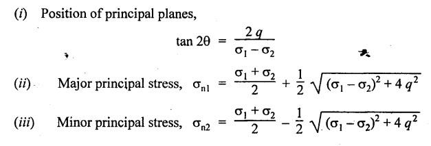


Strength of Materials: Model Questions Papers : Tag: : Model Questions Papers - Strength of Materials - B.E/B.Tech degree examination, may/june 2007
Related Topics
Related Subjects
Strength of Materials
CE3491 4th semester Mechanical Dept | 2021 Regulation | 4th Semester Mechanical Dept 2021 Regulation