Strength of Materials: Model Questions Papers
B.E/B.Tech degree examination, april/may 2011
Model Questions Papers - Strength of Materials
B.E/B.Tech degree examination, april/may 2011: Strength of Materials: Model Questions Papers
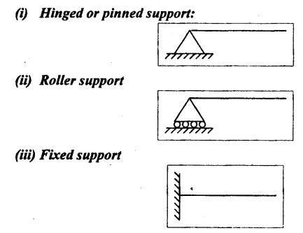
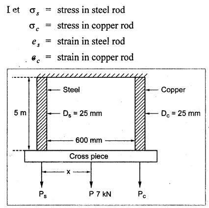
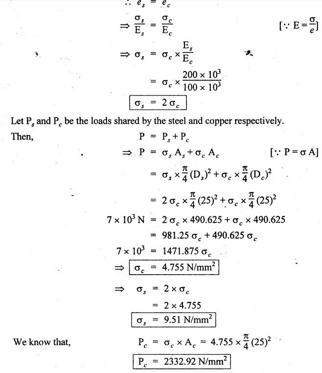
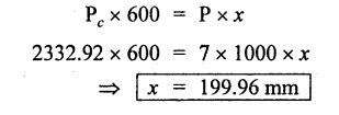
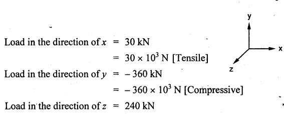
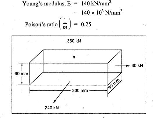
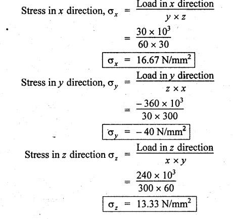
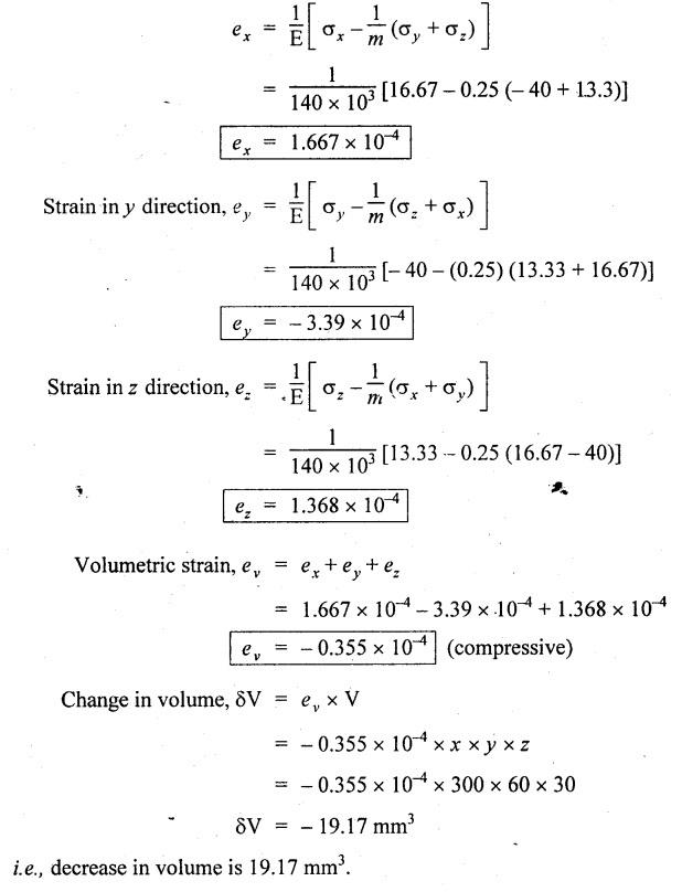
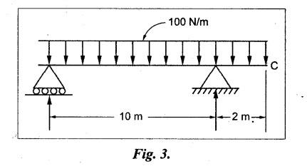
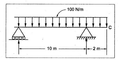
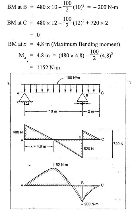
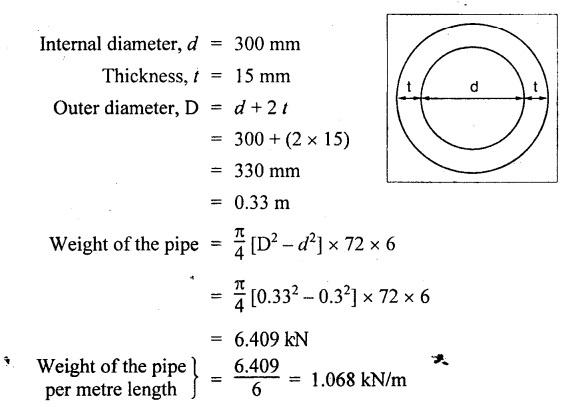
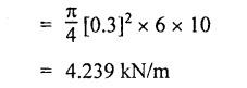
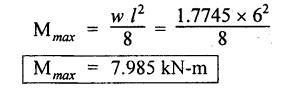
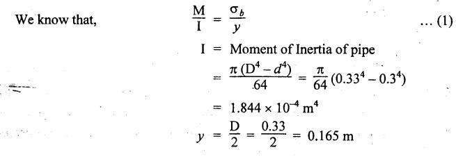
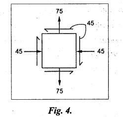
B.E/B.TECH DEGREE EXAMINATION, APRIL/MAY 2011 Fourth Semester - Mechanical Engineering ME 2254 - STRENGTH OF MATERIALS (Common to Automobile Engineering and Production Engineering)(Regulation 2008) (Common to PTME 2254 Strength of Materials for B.E. (Part-Time) Third Semester Mechanical Engineering-Regulation 2009) Time: Three hours Answer ALL Questions. Part A (10 x 2 = 20 marks) Maximum: 100 Marks 1. A rod of diameter 30 mm and length 400 mm was found to elongate 0.35 mm when it was subjected to a load of 65 KN. Compute the modulus of elasticity of the material of this rod. Solution: 2. What is strain energy and write its unit in S.I. system? Ans. Refer Page no. 4.103, Section 4.2. 3. Mention and sketch any two types of supports and cording for the beams. Ans. Types of supports: 4. Sketch the bending stress as well as shear stress distribution for a beam of rectangular cross section. Ans. Refer Anna University Solved Question Paper, Page no. SQ.1, Question - no. 5. Write down the simple torsion formula with the meaning of each symbol for circular cross section. Ans. Refer Page no. 3.86, Question no. 3. 6. Define stiffness of spring and mention its unit in SI system. Ans. Refer Page no. 3.140, Question no. 3. 7. List any four methods of determining slope and deflection of loaded beam. Ans. Refer Page no. 4.1. (i) Double integration method (ii) Macaulay's method (iii) Moment area method (iv) Conjugate beam method 8. The actual length of a column is 10 m. Determine its effective length if both the ends of the column are rigidly fixed. NOT IN SYLLABUS 9. What are assumptions involved in the analysis of thin cylindrical shells? 1. The material of the cylinder is Homogeneous, isotropic and obeys Hook's law. 2. The hoop stress distribution in thin cylinder is uniform over the cross section from inner to outer surface since the thickness of the cylinder is thin. 3. Weight of fluid and material of the cylinder is not taken into accent. 10. Define principle planes. Ans. Refer Page no. 1.192, Question no. 1. PART B - (5 × 16 = 80 marks) 11. (a) Two vertical rods one of steel and other of copper are each rigidly fixed at the top and 600 mm apart. Diameters and lengths of the rods are 25 mm and 5 m respectively. A cross bar fixed to the rods at the lower end carries a load of 7 kN such that the cross bar remains horizontal even after loading. Find the steps in each rod and the position of the load on the cross bar. Assume the modulus of elasticity for steel and copper as 200 kN/mm2 and 100 kN/mm2 respectively. Given: Solution: Since the load is placed in such a manner that the cross piece remains horizontal. Let 'x' be the distance from the steel rod where the load P should be placed so that the cross piece remains horizontal after being loaded. Taking moment about steel rod, Result: (1) Stress in each rod σs = 9.51 N/mm2 σc = 4.755 N/mm2 (2) Position of the load is 199.96 mm from centre of steel rod. 11. (b) A cast iron flat 300 mm long and 30 mm (thickness) × 60 mm (width) uniform cross section, is acted upon by the following forces: 30 kN tensile in the direction of the length 360 kN compression in the direction of the width 240 kN tensile in the direction of the thickness. Calculate the direct strain, net strain in each direction and change in volume of the flat. Assume the modulus of elasticity and Poisson's ratio for cast iron as 140 kN/mm2 and 0.25 respectively. Given: = 240 × 103 N [Tensile] Solution: The Strain along the x direction is 12. (a) Draw the shear force and bending moment diagrams for the beam shown in Fig.3. Also determine the maximum bending moment and location of point of contra flexure. Given: Solution: Taking moment about A The maximum bending moment is situated at a distance of x from the point A where the SF changes its sign. SF equation at that point is RA - 100x = 0 480 - 100 x = 0 x = 4.8 m from point A. i.e., location of point of contra flexure. BM calculation: BM at A = 0 12. (b) A cast iron pipe 300 mm internal diameter, metal thickness 15 mm, is supported at two points 6 m apart. Find the maximum bending stress in the metal of the pipe when it is running full of water. Assume the specific weight of cast iron and water as 72 kN/m3 and 10 kN/m3 respectively. Solution: Weight of water contained in 6 m length of the pipe Weight of water contained per metre length of the pipe For uniformly distributed load, Maximum bending moment, Maximum bending stress: Substitute I, y and M values in equation (1), 13. (a) A steel shaft is required to transmit 75 kW power at 100 r.p.m. and the maximum twisting moment is 30% greater than the mean. Find the diameter of the steel shaft if the maximum stress is 70 N/mm2. Also determine the angle of twist in a length of 3 m of the shaft. Assume the modulus of rigidity for steel as 90 kN/mm2. Ans. Refer Page no. 3.28, Example 3.20. [OR] (b) A helical spring, in which the mean diameter of the coils is 12 times the wire diameter, is to be designed to absorb 300 J energy with an extension of 150 mm. The maximum shear stress is not to exceed 140 N/mm2. Determine the mean diameter of the spring, diameter of the wire which forms the spring and the number of turns. Assume the modulus of rigidity of the material of the spring as 80 kN/mm2. Ans. Refer Page no. 3.128, Example 3.69. 14. (a) A beam of length 6 m is simply supported at the ends and carries two point loads of 48 kN and 40 kN at a distance of 1 m and 3 m respectively from the left support. Compute the slope and deflection under each load. Assume EI = 17000 kN-m2. Ans. Refer Anna University Solved Question Paper, Dec 2008, Problem no. 14(a). [OR] 14. (b) A hollow cast iron strut 150 mm outer and 100 mm in diameter and 8 m long, one end pin jointed and other end is fixed, is subjected to an axial compressive load. Taking factor of safety as 5 and Rankine's constants 550 N/mm2 and 1/1600, calculate the safe load. NOT IN SYLLABUS 15. (a) A cylindrical shell 800 mm in diameter, 3 m long is having 10 mm metal thickness. If the shell is subjected to an internal pressure of 2.5 N/mm2. (i) the change in diameter (ii) the change in length and (iii) the change in volume. Assume the modulus of elasticity and Poisson's ratio of the material of the shell as 200 kN/mm2 and 0.25 respectively. Ans. Refer Page no. 5.11, Example 5.6. [OR] (b) The state of stress (in N/mm2) acting at a certain point of the strained material is shown in Fig.4. Compute (i) The magnitude and nature of principal stresses and (ii) The orientation of principal planes. Ans. Refer Page no. 1.179, Example 1.78.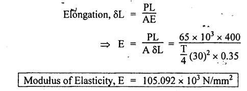


Strength of Materials: Model Questions Papers : Tag: : Model Questions Papers - Strength of Materials - B.E/B.Tech degree examination, april/may 2011
Related Topics
Related Subjects
Strength of Materials
CE3491 4th semester Mechanical Dept | 2021 Regulation | 4th Semester Mechanical Dept 2021 Regulation