Strength of Materials: Model Questions Papers
B.E/B.Tech. degree examination, april/may 2010
Model Questions Papers - Strength of Materials
B.E/B.Tech. degree examination, april/may 2010: Strength of Materials: Model Questions Papers
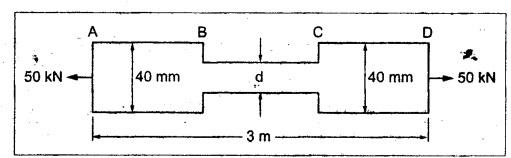
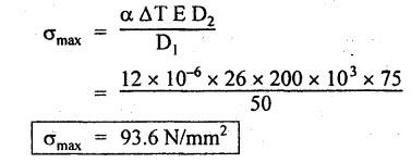
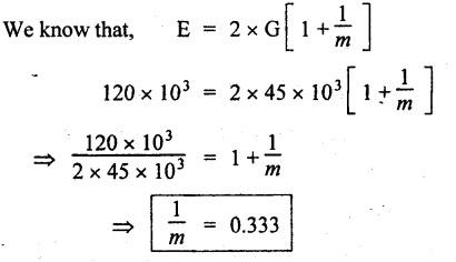
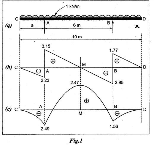
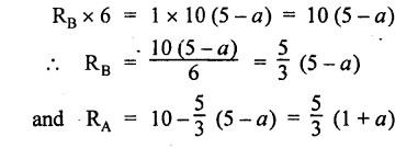
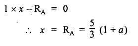
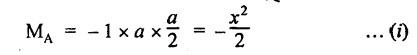
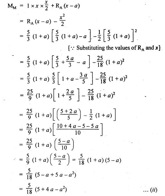
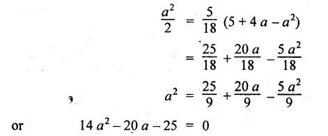
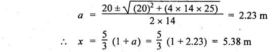
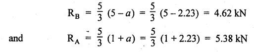
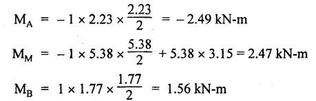
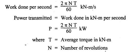
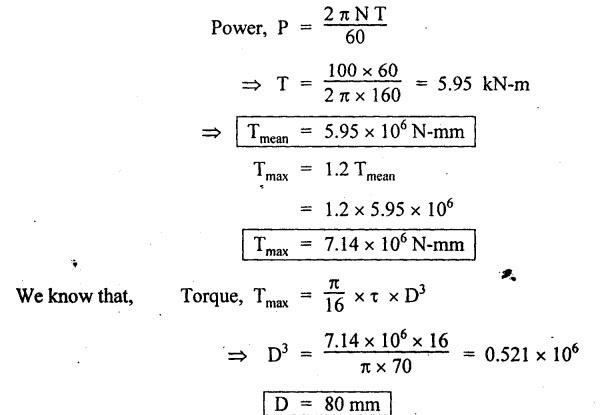
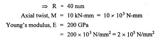
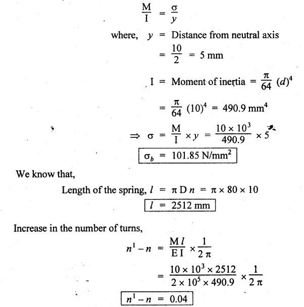
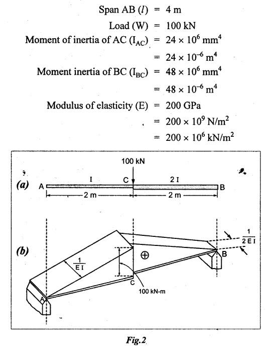
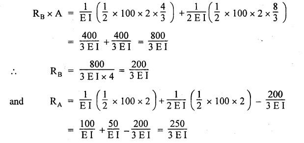
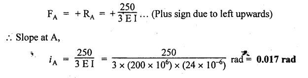
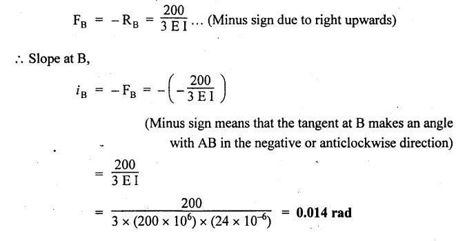
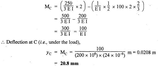
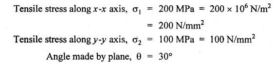
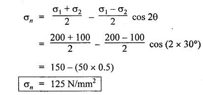
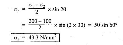
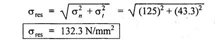
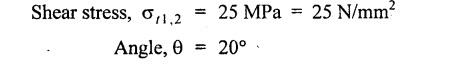
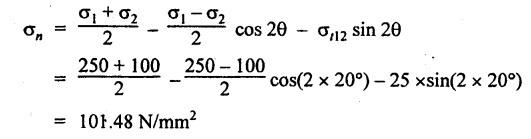
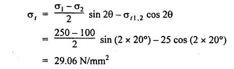
ANNA UNIVERSITY B.E/B.Tech. DEGREE EXAMINATION, APRIL/MAY 2010 Fourth Semester (Mech) (Regulation 2008) ME2254 STRENGTH OF MATERIALS (Common to Automobile Engineering, Production Engg) Time: Three hours Answer ALL Questions. Maximum: 100 Marks Part A (10 × 2 = 20 marks) 1. State Hooke's law. Ans. Refer Page no. 1.125, Question no. 3. 2. Define bulk modulus. Ans. Refer Page no. 1.126, Question no. 11. 3. What do you understand by the term 'Point of contraflexure'? Ans. Refer Page no. 2.122, Question no. 25. 4. What is the value of bending moment corresponding to a point having a zero shear force? The value of bending moment is maximum when the shear force changes its sign or zero. In a beam, that point is considered as maximum bending moment. 5. Write the assumption for finding out the shear stress of a circular shaft subjected to torsion. Ans. Refer Page no. 3.86, Question no. 2. 6. Define the term stiffness of a spring. Ans. Refer Page no. 3.140, Question no. 3. 7. What is the relation between slope, deflection and radius of curvature of a beam? 8. What are the assumptions made in Euler's column theory? NOT IN SYLLABUS 9. List out the modes of failure in thin cylindrical shell due to an internal pressure. Ans. Refer Page no. 5.1, Section 5.1.2. 10. What do you mean by principal plane? Ans. Refer Page no. 1.192, Question no. 1. Part B - (5 × 16 = 80 marks) 11. (a) (i) An alloy circular bar ABCD 3 m long is subjected to a tensile force of 50 kN as shown in figure. If the stress in the middle portion BC is not to exceed 150 MPa, then what should be its diameter? Also find the length of the middle portion, if the total extension of the bar should not exceed by 3 mm. Take E = 100 GPa. (12) Ans. Refer Page no. 1.16, Example 1.9. [Ans. D2 = 20.6 mm; L2 = 1.64 m] (ii) A circular bar rigidly fixed at its both ends uniformly tapers from 75 mm at one end to 50 mm at the other end. If its temperature is raised through 26 K, What will be the maximum stress developed in the bar. Take E as 200 GPa and a as 12 × 10-6/K for the bar material. Given: Diameter of the larger end, D2 = 75 mm Diameter of the smaller end, D1 = 50 mm Rise in temperature, ∆T = 26 K Young's modulus, E = 200 GPa = 200 × 103 N/m2 Coefficient of linear expansion, α = 12 × 10-6/K To find: Maximum stress, σmax Solution: We know that, maximum stress developed in the bar, [OR] (b) (i) In an experiment, a bar of 30 mm diameter is subjected to a pull of 60 kN. The measured extension on gauge length of 200 mm is 0.09 mm and the change in diameter is 0.0039 mm. Calculate the Poisson's ratio and the values of the three modulii. Ans. Refer Page no. 1.85, Example 1.41. [Ans. 1/m = 0.289; E = 188.62 × 10³ N/mm2 ; K = 148.98 × 10³ N/mm2; G = 72.66 ×10³ N/mm2] (ii) An alloy specimen has modulus of elasticity of 120 GPa and modulus of rigidity of 45 GPa. Determine the Poisson's ratio of the material. Given: E = 120 GPa = 120 × 109 N/m2 = 120 × 103 N/mm2 G = 45 GPa = 45 × 103 N/mm2 To find: Poisson's ratio (1/m) Solution: 12. (a) A simply supported beam of 4 m span is carrying loads as shown in Figure. Draw the shear force and bending moment diagrams for the beam. Ans. Refer Page no. 2.40, Example 2.15. [OR] (b) A horizontal beam 10 m long is carrying a uniformly distributed load of 1 kN/m. The beam is supported on two supports 6 m apart. Find the position of the supports, so that bending moment on the beam is as small as possible. Also draw the shear force and bending moment diagrams. Given: Total length of beam = 10 m; Uniformly distributed load (w) = 1 kN/m and span (l) = 6 m Let a be the distance between the support A and the left end of beam as shown in Fig. 1(a). Taking moments about, From the geometry of the figure, we find that the maximum negative bending moment will be at either of the two supports and the maximum positive bending moment will be in the span AB. Let the maximum positive bending moment be at M at a distance of x from C. Since the shear force at M is zero, therefore We know that the bending moment at A, and bending moment, where shear force is zero (i.e., at a distance of x from C), Equating (i) and (ii) and ignoring the nature of MA, Solving it as a quadratic equation for a, Now reaction at B, Shear force diagram: The shear force diagram is shown in Fig. 1(b), and the values are given below: FC = 0 FA = 0 -1 × 2.23 + 5.38 = +3.15 kN FB = +3.15 - 1 × 6 + 4.62 = +1.77 kN FD = +1.77 - 1.77 = 0 Bending moment diagram: The bending moment diagram is drawn in Fig.1(c), and the values are given below: MC = 0 MD = 0 13. (a) (i) obtain a relation for the torque and power, a solid shaft can transmit. (8) The main purpose of a shaft is to transmit power from one shaft to another. The rotating shaft which transmits power from one of its ends to another. Let, N = Number of revolutions per minute T = Average torque in KN-m Work done per minute = Force × Distance = T × 2πN = 2πNT [OR] (ii) A solid steel shaft has to transmit 100 kW at 160 r.p.m. Taking allowable shear stress as 70 MPa, find the suitable diameter of the shaft. The maximum torque transmitted in each revolution exceeds the mean by 20%. (8) Given: Power, P = 100 kW Speed, N = 160 r.p.m. Shear stress, τ = 70 MPa = 70 N/mm2 Tmax = 1.2 T mean To find: Diameter of the shaft, D Solution: We know that, [OR] (b) (i) Derive an equation for deflection of an open coiled helical spring. (8) Ans. Refer Page no. 3.98, Section 3.2.9. (ii) A closely coiled helical spring is made up of 10 mm diameter steel wire having 10 coils with 80 mm mean diameter. If the spring is subjected to an axial twist of 10 kN-mm, determine the bending stress and increase in the number of turns. Take E as 200 GPa. Given: Diameter of the wire, d = 10 m Number of coils, n = 10 Diameter of the coil, D = 80 mm To find: Bending stress, σb 2. Increase in the number of turns (n' – n) Solution: We know that, 14. (a) A cantilever AB, 2 m long, is carrying a load of 20 kN at free end and 30 kN at a distance 1 m from the free end. Find the slope and deflection at the free end. Take E = 200 GPa and I = 150 × 106 mm4. Ans. Refer Page no. 4.46, Example 4.1. [OR] (b) A simply supported beam AB of span 4 m, carrying a load of 100 kN at its mid span C has cross sectional moment of inertia 24 × 106 mm4 over the left half of the span and 48 × 106 mm4 over the right half. Find the slope at two supports and the deflection under the load. Take E = 200 GPa. Given: Slope at the two supports: We know that the bending moment will be zero at A and B and increase by a straight line law to, Now draw the conjugate beam as shown in Fig.2(b). Taking moments about A, We know that shear force at A, Similarly, shear force at B, Deflection under the load: We know that bending moment at C (i.e., under the load) conjugate beam, 15. (a) (i) A cylindrical vessel 2 m long and 500 mm in diameter with 10 mm thick plates is subjected to an internal pressure of 3 MPa. Calculate the change in volume of the vessel. Take E = 200 GPa and Poisson's ratio = 0.3 for the vessel material. Ans. Refer Page no. 5.11, Example 5.6. (ii) A spherical shell of 2 m diameter is made up of 10 mm thick plates. Calculate the change in diameter and volume of the shell, when it is subjected to an internal pressure of 1.6 MPa. Take E = 200 GPa and 1/m = 0.3. Ans. Refer Page no. 5.22, Example 5.15. [OR] (b) (i) A point in a strained material is subjected to two mutually perpendicular tensile stress of 200 MPa and 100 MPa. Determine the intensities of normal, shear and resultant stresses on a plane inclined at 30° with the axis of the minor tensile stress. Given: Solution: We know that, Normal stress on the inclined plane, Shear stress on the inclined plane, Resultant stress on the inclined plane (ii) A point is subjected to a tensile stress of 250 MPa in the horizontal direction and another tensile stress of 100 MPa in the vertical direction. The point is also subjected to a simple shear stress of 25 MPa, such that when it is associated with the major tensile stress, it tends to rotate the element in the clockwise direction. What is the magnitude of the normal and shear stresses on a section inclined at an angle of 20° with the major tensile stress? Given: Tensile stress in horizontal x-x direction σ1 = 250 MPa = 250 N/mm2 Tensile stress in vertical y-y direction σ2 = 250 MPa = 100 N/mm2 Solution: We know that, Magnitude of normal stress, Magnitude of shear stress,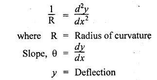

Strength of Materials: Model Questions Papers : Tag: : Model Questions Papers - Strength of Materials - B.E/B.Tech. degree examination, april/may 2010
Related Topics
Related Subjects
Strength of Materials
CE3491 4th semester Mechanical Dept | 2021 Regulation | 4th Semester Mechanical Dept 2021 Regulation