Strength of Materials: Model Questions Papers
B.E./B.Tech. Degree Examination, May/June 2014
Model Questions Papers - Strength of Materials
B.E./B.Tech. Degree Examination, May/June 2014 : Strength of Materials: Model Questions Papers
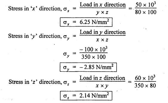
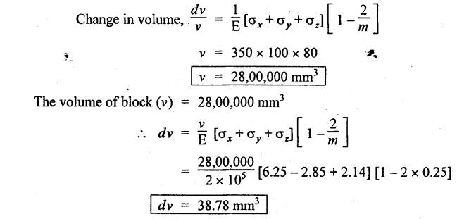
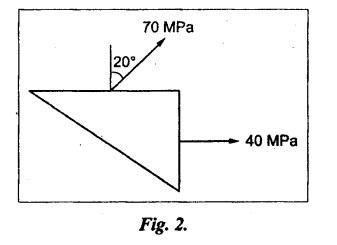
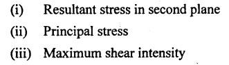
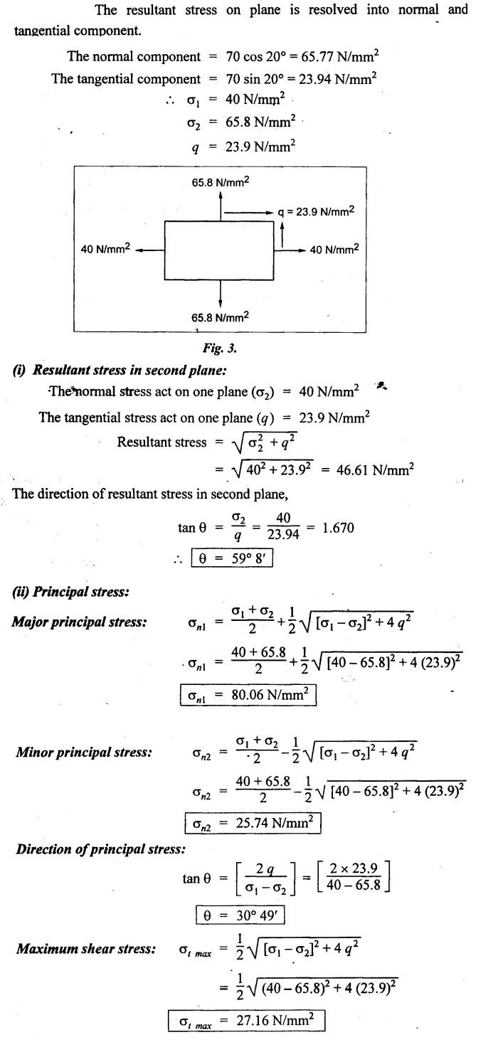
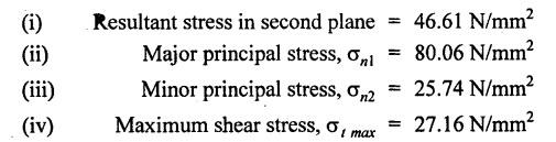
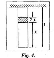
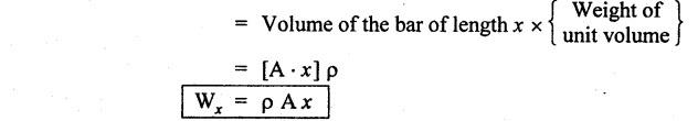
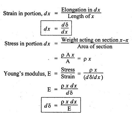
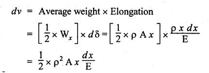
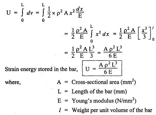
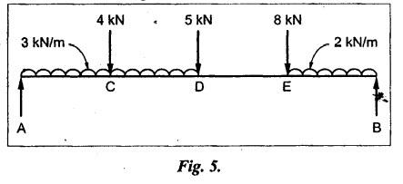
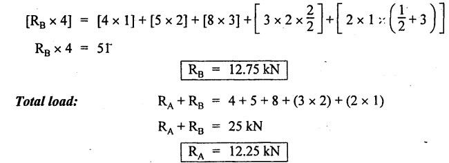
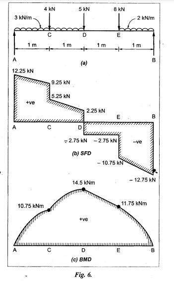
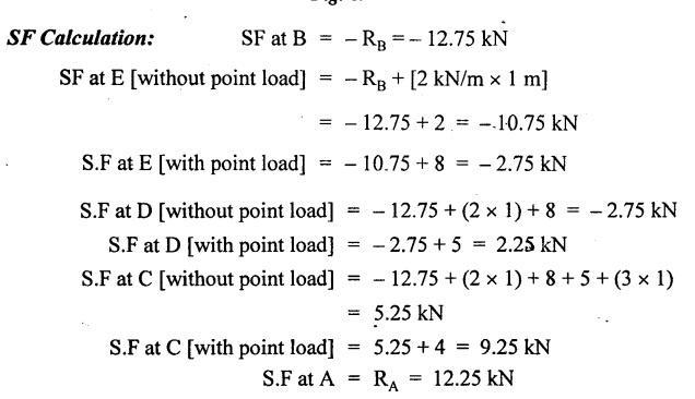
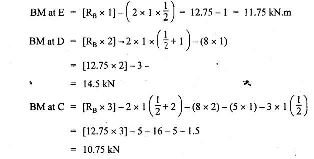
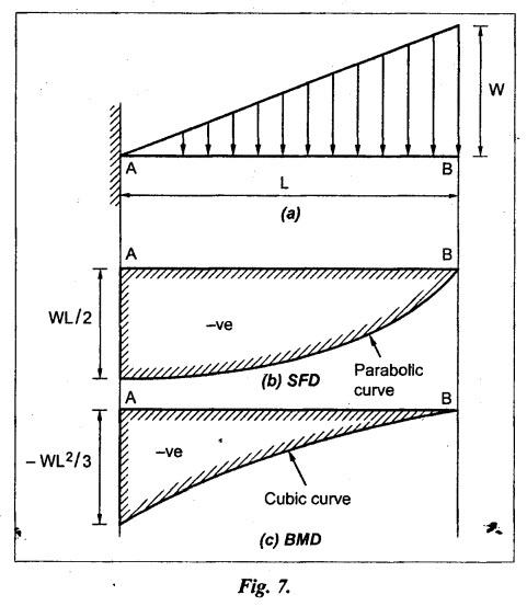
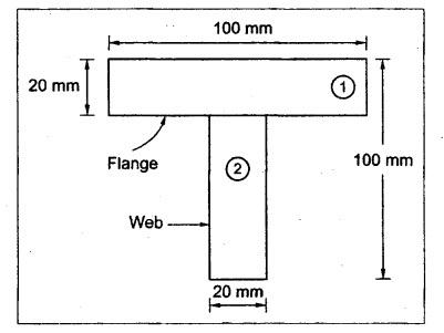
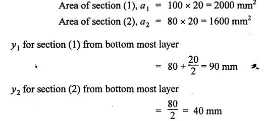
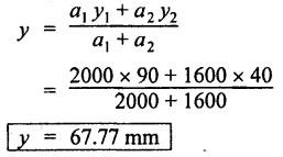
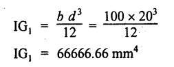
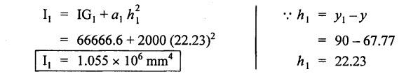
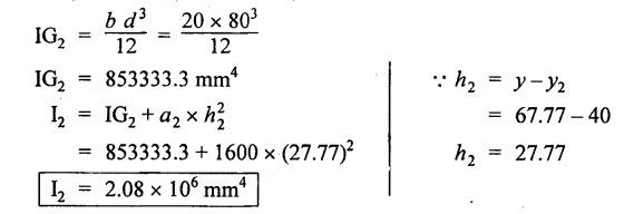
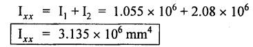
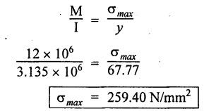
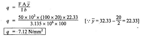
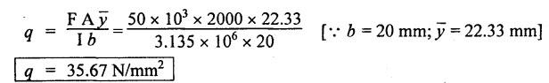
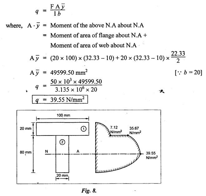
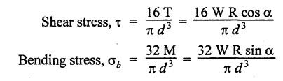
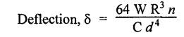
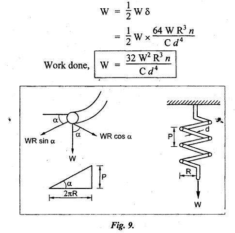
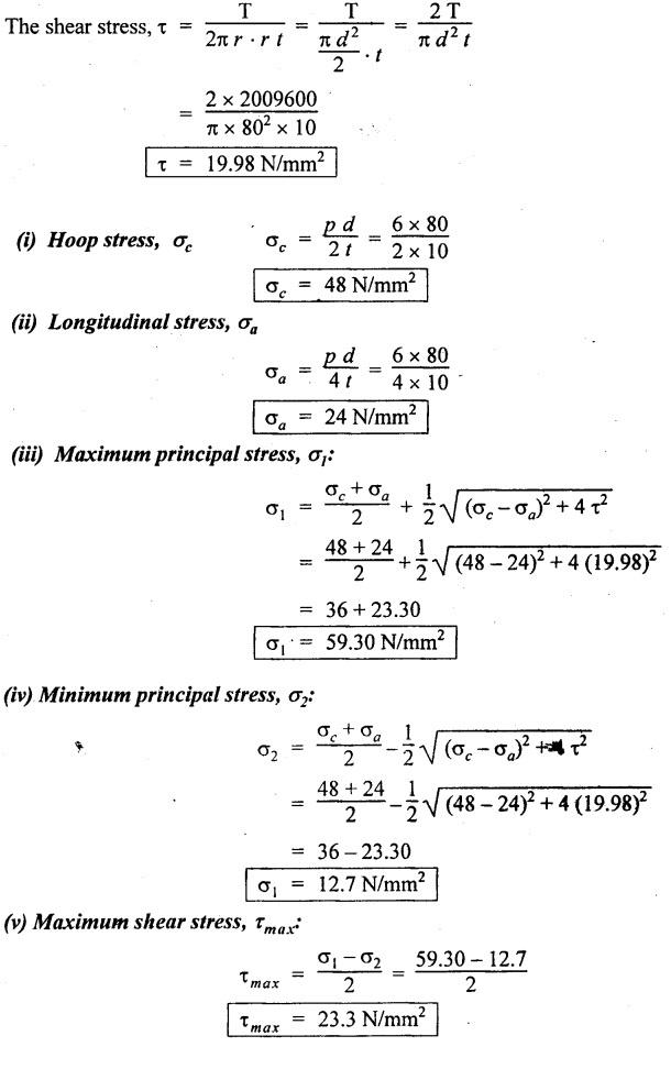
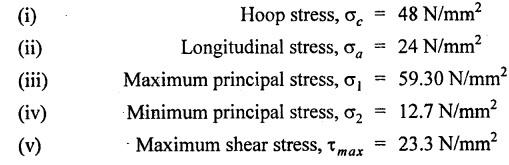
B.E./B.Tech. Degree Examination, May/June 2014 Fourth Semester - Mechanical Engineering STRENGTH OF MATERIALS (Common to Production Engineering and Automobile Engineering) (Regulation 2008/2010) (Common to PTME 2254 - Strength of Materials for B.E. (Part-Time) Third Semester, Mechanical Engineering, Regulation 2009) Time: Three hours Maximum: 100 Marks Answer ALL Questions. Part A - (10 × 2 = 20 Marks) 1. What is Bulk modulus of material? Ans. Refer Page no. 1.126, Question no. 11. 2. Define Resilience and Proof Resilience. Ans. Refer Page no. 4.103, Section 4.2.1 and 4.2.2. 3. Draw a typical shear force and bending moment diagram of a simply supported beam of span 'L', carrying a point load 'P' at mid span. Ans. Refer Page no. 2.119, Question no. 15. 4. Mention the assumptions made in the theory of simple bending. Ans. Refer Page no. 2.172, Question no. 3. 5. Define torsion and give at least two practical example for it. Ans. Refer Page no. 3.86, Question no. 1. 6. Write short notes on types of springs. Ans. Refer Page no. 3.140, Question no. 2. 7. State the Mohr's theorem I and II. Ans. Refer Page no. 4.100, Question no. 8. 8. What is equivalent length of a column? NOT IN SYLLABUS 9. How do you classify a cylinder or a shell in to thick or thin? Ans. Refer Page no. 5.34, Question no. 1. 10. Define principle plane. Ans. Refer Page no. 1.192, Question no. 1. PART B (5 × 16 = 80 marks) 11. (a) (i) A bar of 30 mm diameter is subjected to a pull of 60 kN. The measured extension on gauge length of 200 mm is 0.09 mm and the change in diameter is 0.0039 mm. Calculate the Poisson's ratio and the value of the three moduli. (8) Ans. Refer Page no. 1.85, Example no. 1.41. 11. (a) (ii) A rectangular block 350 mm long, 100 mm wide and 80 mm thick is subjected to axial load as follows. 50 kN tensile in the direction of length, 100 kN compression in the direction of thickness and 60 KN tensile in the direction of breadth. Determine the change in volume, bulk modulus, modulus of rigidity. Take E = 2 × 10 N/mm2 and Poisson's ratio = 0.25. Given: Young's modulus (E) = 2 × 10⁵ N/mm2 Poisson's ratio (1/m) = 0.25 Load in 'x' direction = 50 kN [tensile] Load in 'y' direction = -100 kN [compression] Load in 'z' direction = 60 kN [tensile] To find: (i) Change in volume (δv) (ii) Bulk modulus (K) (iii) Modulus of rigidity (C) Solution: We know that, We know that the relation between Young's modulus (E) and modulus of rigidity (C) and Bulk modulus (K). Result: [OR] 11. (b) (i) A resultant tensile stress of 70 MPa is acting over as shown in the Fig.2. Another direct tensile stress of 40 MPa is acting over a plane, which is at right angle to the previous one. Find the resultant stresses in the second plane, the principle planes and stresses and the plane of maximum shear intensity. Given: To find: Solution: Result: 11. (b) (ii) Determine the strain energy due to self weight of a bar of uniform cross section 'a' having length 'I' which is hanging vertically down. Solution: Consider an element at a distance 'x' from the lower end of the bar as shown in Fig. below. Let 'dx' be the thickness of the element. The section 'x-x' will be acted upon by the weight of the bar of length 'x'. Let Wx = Weight of the bar of length 'x' As a result of this weight, the portion 'dx' will experience a small elongation 'dδ', then Now the strain energy stored in portion 'dx' is given by Total strain energy stored within the bar due to its self weight W is obtained by integrating the above equation from 0 to L. 12. (a) (i) Draw the shear force and bending moment diagram for the simply supported beam shown in Fig.5. Given: As shown in Fig.5. To find: SFD and BMD Solution: Taking moment about A, SF Calculation: Joint all the values by straight inclined line as shown in SFD. BM calculation: BM at B = 0 BM at A = 0 Join the values between D and E by straight lien and all other values by parabolic curves. Result: The SFD and BMD are shown in Fig.6(b) and (c) respectively. 12. (a) (ii) Draw the shear force and bending moment diagram for a cantilever carrying load whose intensity varies uniformly from zero at the fixed end to 'w' per unit run at the free end. [OR] 12. (b) A T-section of a simply supported beam has the width of flange 100 mm, overall depth = 100 mm, thickness of flange and stem = 20 mm. Determine the maximum stress in beam when a bending moment of 12 kN-m is acting on the section. Also calculate the shear stress at neutral axis and at the junction of web and flange when shear force of 50 kN acting on beam. Given: Bending moment = 12 kN.m = 12 × 106 N.mm Load = 50 KN 50 × 103 N To find: (i) The maximum stress in beam when a bending moment of 12 kN.m. (ii) Shear stress at the neutral axis and junction of web and flange. Solution: For unsymmetrical section, the centre of gravity of the section is placed is 'y' mm from the bottom face. The 'y' may be calculated by using the formula, Moment of inertia of rectangle section (1) about an axis through its C.G and parallel to x-x axis. From parallel axis theorem, moment of inertia of rectangular section (1) from x-x axis. Similarly section (2), The moment of inertia of whole section about x-x axis. (i) Determine the maximum stress in beam when a bending moment of 12 kN.m. We know that (ii) Calculate the shear stress in the neutral axis and at the junction of web and flange when shear force F = 50 kN. Shear stress in flange at the junction with web Shear stress distribution in the web: The shear stress will be maximum at N.A. Hence shear stress at the N.A is given by Result: (i) The maximum shear in beam when a bending moment of 12 kN.m, σmax = 259.40 N/mm2 (ii) The shear stress on flange = 7.12 N/mm2 (iii) The shear stress on web = 39.55 N/mm2 13. (a) The internal and external diameter of a hollow shaft is in the ratio of 2: 3. The hollow shaft is to transmit a 400 kW power at 120 rpm. The maximum expected torque is 15% greater than the mean value. If the shear stress is not to exceed 50 MPa, find section of the shaft which would satisfy the shear stress and twist conditions. Take G = 0.85 × 10⁵ MPa. Ans. Refer Page no. 3.37, Example 3.27. Assume: L = 1 m and θ = 1° First case: External diameter, D = 166.43 mm Internal diameter, d = 110.84 mm Second case: External diameter, D = 133 mm Internal diameter, d = 88.64 mm From the above two cases, we find that suitable external and internal diameter of the shaft is External diameter, D = 166.43 mm Internal diameter, d = 110.84 mm [OR] 13. (b) Determine the bending stress, shear stress and total work done on an open coiled helical spring subjected to axial force having mean radius of each coil as 'r' and 'n" numbers of turns. Solution: Consider an open coiled spring subjected to an axial load as shown in Fig.9. The 'p' is the pitch of the coil and u is the vertical distance transversed as the wire goes around the helical path in one turn. Let 'd' is the diameter of the wire and 'R' is the mean radius of the coil. W = Axial load P = Pitch of the spring d = Wire diameter R = Mean radius of the spring Axial load: Torque, T = WR cos α Bending moment, M = WR sin α Work done: Refer Page no. The average external work done on the spring under load, 14. (a) A beam of length 6 m is simply supported at its ends and carries two point leads of 48 kN at a distance of 1 m and 3 m respectively from left and support. Find the deflection under each load, the maximum deflection and the point at which occurs. Assume E = 2 × 10⁵ MPa and I = 85 × 106 MPa. Use Macaulay's method. Ans. Refer Anna University Solved Question Paper, May 2007, Problem no. 14 (a). Deflection at point C, yC = - 10.03 mm Deflection at point D, yD = - 18.82 mm Maximum deflection occurs at x = 2.88 m Maximum deflection, ymax = - 18.85 mm [OR] 14. (b) Find the Euler's crippling load for a column with one end fixed and other end free. NOT IN SYLLABUS 15. (a) A cylindrical shell 1 m dia and 3 m length is subjected to an internal pressure of 2 MPa. Calculate the maximum thickness if the stress should not exceed 50 MPa. Find the change in dia and volume of shell. Assume Poisson's ratio of 0.3 and Young's modulus of 200 kN/mm2. (16) Ans. Refer Page no. 5.32, Example no. 5.22. [OR] 15. (b) A thin cylindrical tube 80 mm internal diameter and 5 mm thick is closed at its ends. It is subjected to an internal pressure of 6 N/mm2 and a torque of 2009600 kN.m. Find the hoop stress, longitudinal stress, maximum and minimum principle stresses and maximum shear stress. (16) Given Data: Internal diameter, d = 80 mm Thickness of tube, t = 5 mm Internal pressure, P = 6 N/mm2 Torque, T = 2009600 N.mm To find: (i) Hoop stress, σC (ii) Longitudinal stress, σa (iii) Maximum and minimum principal stress, σ1, σ2 (iv) Maximum shear stress, τmax Solution: Result: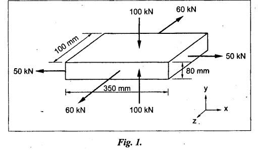


Strength of Materials: Model Questions Papers : Tag: : Model Questions Papers - Strength of Materials - B.E./B.Tech. Degree Examination, May/June 2014
Related Topics
Related Subjects
Strength of Materials
CE3491 4th semester Mechanical Dept | 2021 Regulation | 4th Semester Mechanical Dept 2021 Regulation