Hydraulics and Pneumatics: Unit IV: Pneumatic and Electro Pneumatic Systems
automatic pneumatic cylinder reciprocating system
Pneumatic and Electro Pneumatic Systems - Hydraulics and Pneumatics
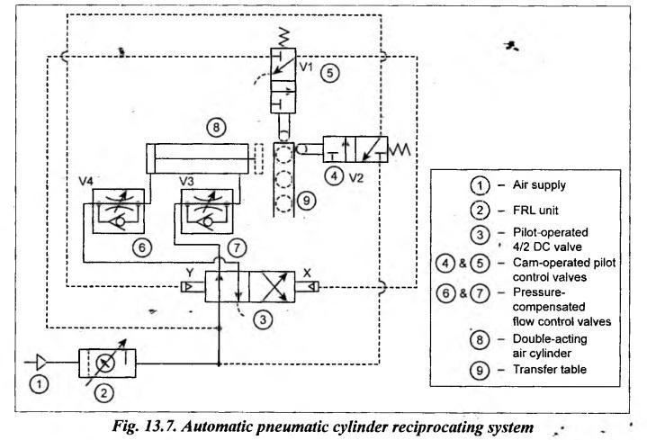
Fig.13.7 illustrates a circuit that produces automatic reciprocation of the pneumatic cylinder.
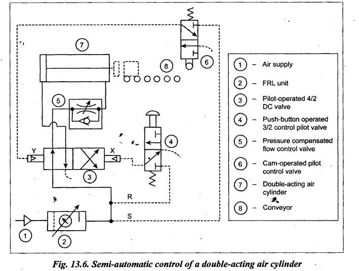
AUTOMATIC PNEUMATIC CYLINDER RECIPROCATING SYSTEM (Continuous Reciprocation Circuit) (Automatic Material Handling Circuit) Fig.13.7 illustrates a circuit that produces automatic reciprocation of the pneumatic cylinder. This type of automatic circuits have many applications in the material handling field. This circuit uses two cam-operated pilot control valves, a pilot-pressure operated 4/2 DC valve, two flow control valves, and a double-acting air cylinder. Extension: When first workpiece on the transfer table contacts and depresses cam roller of pilot control valve V1, the air flows to pilot chamber X of 4/2 DC valve shifting its position to right mode. When the 4/2 DC valve is shifted to its right envelope flow path configuration, the compressed air flows into the blind end of the cylinder and thus the cylinder extends. The speed of the, cylinder is controlled by the flow control valve (V3) through which air is being exhausted from the rod end. Now the workpiece moves from the transfer table onto gravity conveyor. Retraction: As the piston approaches its end of the cylinder stroke, the cam roller of pilot control valve V2 is depressed and air flows to pilot chamber Y of 4/2 DC valve shifting its position to left mode. When the 4/2 DC valve is shifted to its left envelope flow path extends. At the same time, the air at the rod end of the cylinder is exhausted into the atmosphere directly. It may be noted that the piston out speed of the cylinder is controlled by flow control valve. Retraction: Once the extension stroke of the cylinder completes, the cam-operated pilot control valve is tripped and air flows to pilot chamber Y of 4/2 DC valve shifting its position. When the 4/2 DC valve is shifted to its left mode, the compressed air flows to the rod end of the cylinder and thus the cylinder retracts. At the same time, the air at the blind end of the cylinder is exhausted to the atmosphere. For the next cycle, again the operator only needs to momentarily press the push-button. Thus in this semi-automatic circuit, once the operator momentarily presses the push-button, the circuit completes its cycle automatically. This circuit may be used as semi-automatic material handling circuit for pushing the large boxes from transfer table onto conveyor, as shown in Fig.13.6. configuration, the compressed air flows into the rod end of the cylinder and thus the cylinder extends. Now the speed of the cylinder is controlled by the flow control valve (V4) through which air is being exhausted from the blind end. Now the second workpiece is fed in and the next cycle automatically starts. Thus the sequence repeats and the cylinder reciprocates continuously without the operator's help.1. Circuit
2. Operation
Hydraulics and Pneumatics: Unit IV: Pneumatic and Electro Pneumatic Systems : Tag: : Pneumatic and Electro Pneumatic Systems - Hydraulics and Pneumatics - automatic pneumatic cylinder reciprocating system
Related Topics
Related Subjects

Hydraulics and Pneumatics
ME3492 4th semester Mechanical Dept | 2021 Regulation | 4th Semester Mechanical Dept 2021 Regulation