Hydraulics and Pneumatics: Unit IV: Pneumatic and Electro Pneumatic Systems
Automatic pneumatic cylinder reciprocating system
Pneumatic and Electro Pneumatic Systems - Hydraulics and Pneumatics
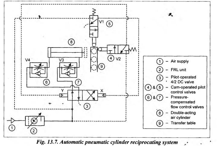
Fig.13.7 illustrates a circuit that produces automatic reciprocation of the pneumatic cylinder.
AUTOMATIC PNEUMATIC CYLINDER RECIPROCATING SYSTEM (Continuous Reciprocation Circuit) (Automatic Material Handling Circuit) Fig.13.7 illustrates a circuit that produces automatic reciprocation of the pneumatic cylinder. This type of automatic circuits have many applications in the material handling field. This circuit uses two cam-operated pilot control valves, a pilot-pressure operated 4/2 DC valve, two flow control valves, and a double-acting air cylinder. Extension: When first workpiece on the transfer table contacts and depresses cam roller of pilot control valve V1, the air flows to pilot chamber X of 4/2 DC valve shifting its position to right mode. When the 4/2 DC valve is shifted to its right envelope flow path configuration, the compressed air flows into the blind end of the cylinder and thus the cylinder extends. The speed of the cylinder is controlled by the flow control valve (V3) through which air is being exhausted from the rod end. Now the workpiece moves from the transfer table onto gravity conveyor. Retraction: As the piston approaches its end of the cylinder stroke, the cam roller of pilot control valve V2 is depressed and air flows to pilot chamber Y of 4/2 DC valve shifting its position to left mode. When the 4/2 DC valve is shifted to its left envelope flow path1. Circuit
2. Operation
Hydraulics and Pneumatics: Unit IV: Pneumatic and Electro Pneumatic Systems : Tag: : Pneumatic and Electro Pneumatic Systems - Hydraulics and Pneumatics - Automatic pneumatic cylinder reciprocating system
Related Topics
Related Subjects

Hydraulics and Pneumatics
ME3492 4th semester Mechanical Dept | 2021 Regulation | 4th Semester Mechanical Dept 2021 Regulation